

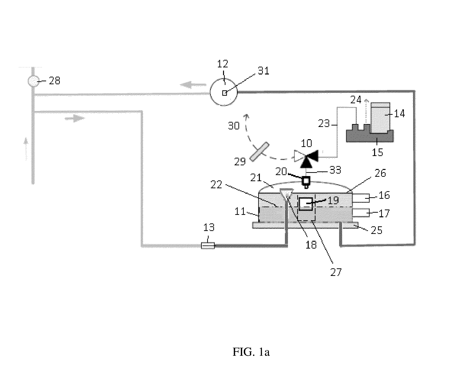
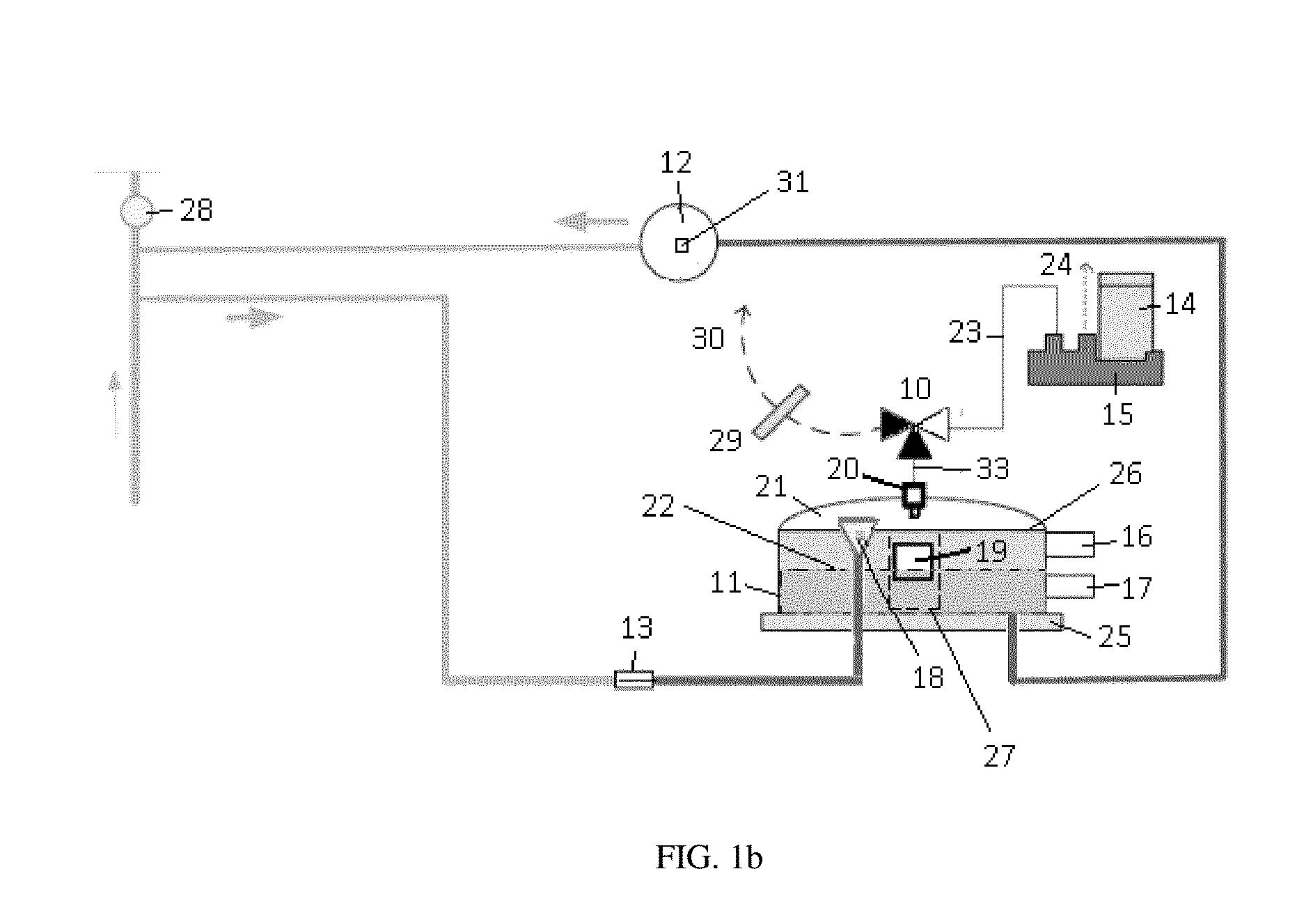
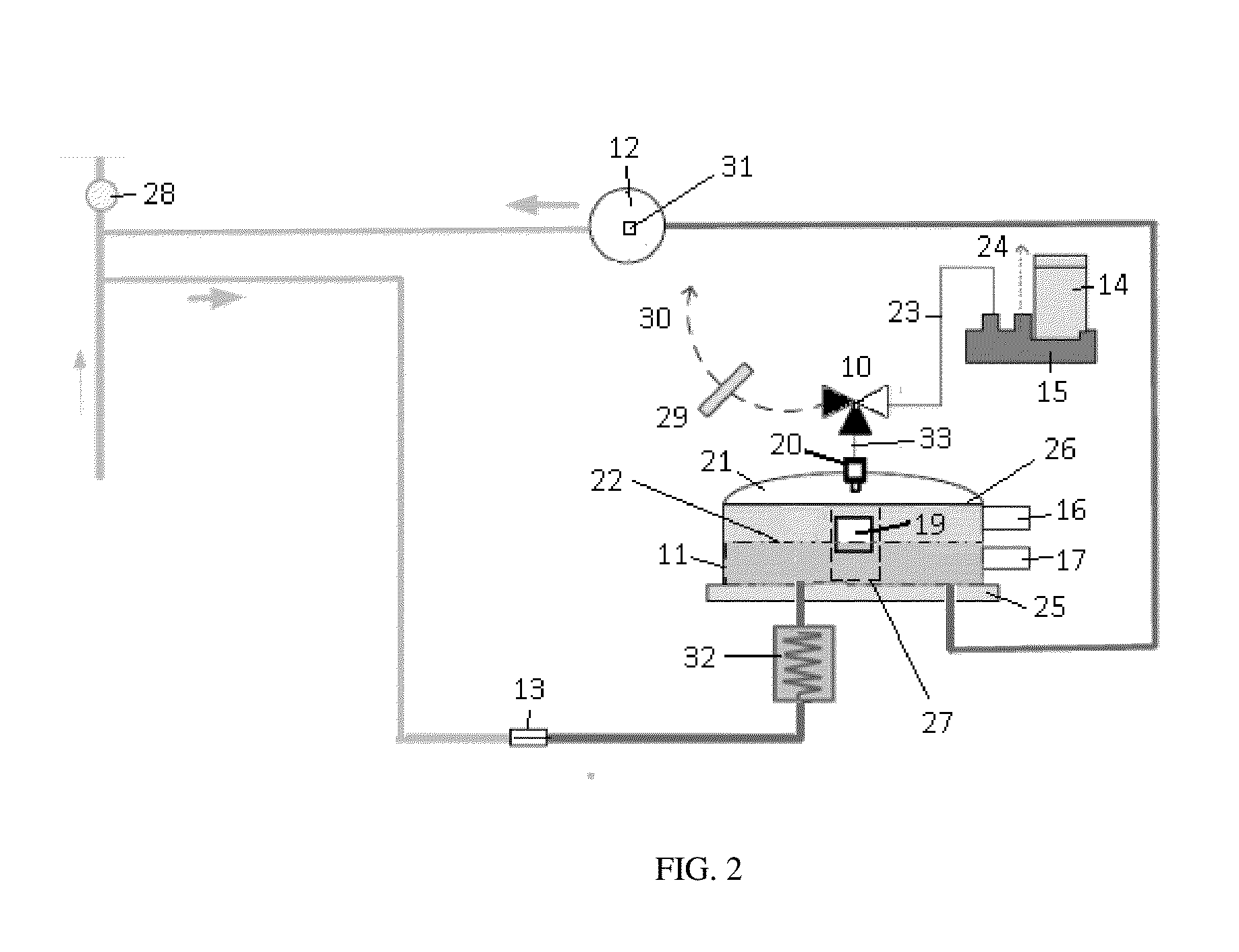
Degassing system for dialysis
a dialysis and dialysis technology, applied in the field of dialysis dialysis, can solve the problems of reducing diffusive clearance, creating bubbles, dangerous conditions for patients, etc., and achieve the effect of raising the liquid level and reducing the fluid level
- Summary
- Abstract
- Description
- Claims
- Application Information
AI Technical Summary
Benefits of technology
Problems solved by technology
Method used
Image

Examples
Embodiment Construction
[0080]Unless defined otherwise, all technical and scientific terms used herein generally have the same meaning as commonly understood by one of ordinary skill in the relevant art.
[0081]The articles “a” and “an” are used herein to refer to one or to more than one (i.e., to at least one) of the grammatical object of the article. By way of example, “an element” means one element or more than one element.
[0082]The term “cartridge” refers to any container designed to contain a powder, fluid, or gas made for ready connection to a device or mechanism. The container can have one or more compartments. Instead of compartments, the container can also be comprised of a system of two or more modules connected together to form the cartridge wherein the two or more modules once formed can be connected to a device or mechanism.
[0083]The term “carbon dioxide sensor” refers to devices that can detect or measure the concentration of carbon dioxide in a liquid or gas.
[0084]The terms “communicate” and “...
PUM
| Property | Measurement | Unit |
|---|---|---|
| absolute pressure | aaaaa | aaaaa |
| absolute pressure | aaaaa | aaaaa |
| absolute pressure | aaaaa | aaaaa |
Abstract
Description
Claims
Application Information