Insulation system

Inactive Publication Date: 2016-06-16
CHALLENOR HARRILL ASHLEY
View PDF1 Cites 2 Cited by
  • Summary
  • Abstract
  • Description
  • Claims
  • Application Information

AI Technical Summary

Benefits of technology

[0033]In one form of the invention, the reinforcing mesh embedded in the low density foam has its fibres aligned in a square mesh with the fibres 90 degrees to each other with one set of fibres running longitudinally to the low density foam moulding and the other set of fibres transversely located. In this configuration, the fibreglass reinforcing mesh reduces the modulus of expansion and contraction of the low density foam to approximately that of stainless steel over the range of temperatures from −200 degrees Celsius to plus 100 degrees Celsius, namely between 15 to 20×10−6 m

Problems solved by technology

The installation process requires highly skilled labour, is time consuming, wasteful of materials and access to the pipe is often limited and the time taken to complete the installation is lengthy.
Skilled insulation installers are difficult to find for most remote projects and reducing the skills requirement will assist in completing the insulation work earlier.
Traditional cold insulation

Method used


Image

  • Insulation system
  • Insulation system
  • Insulation system

Examples


first embodiment

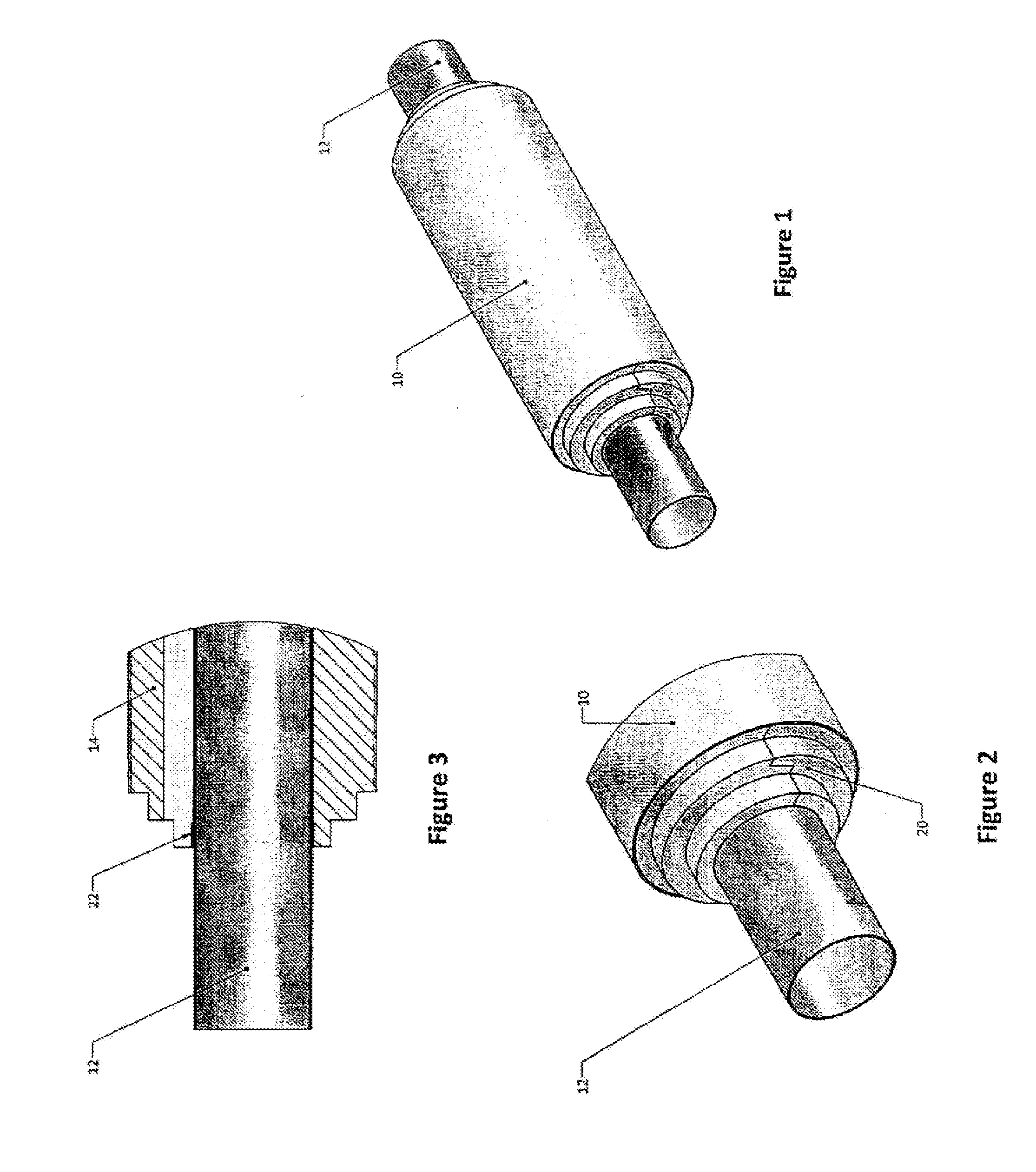
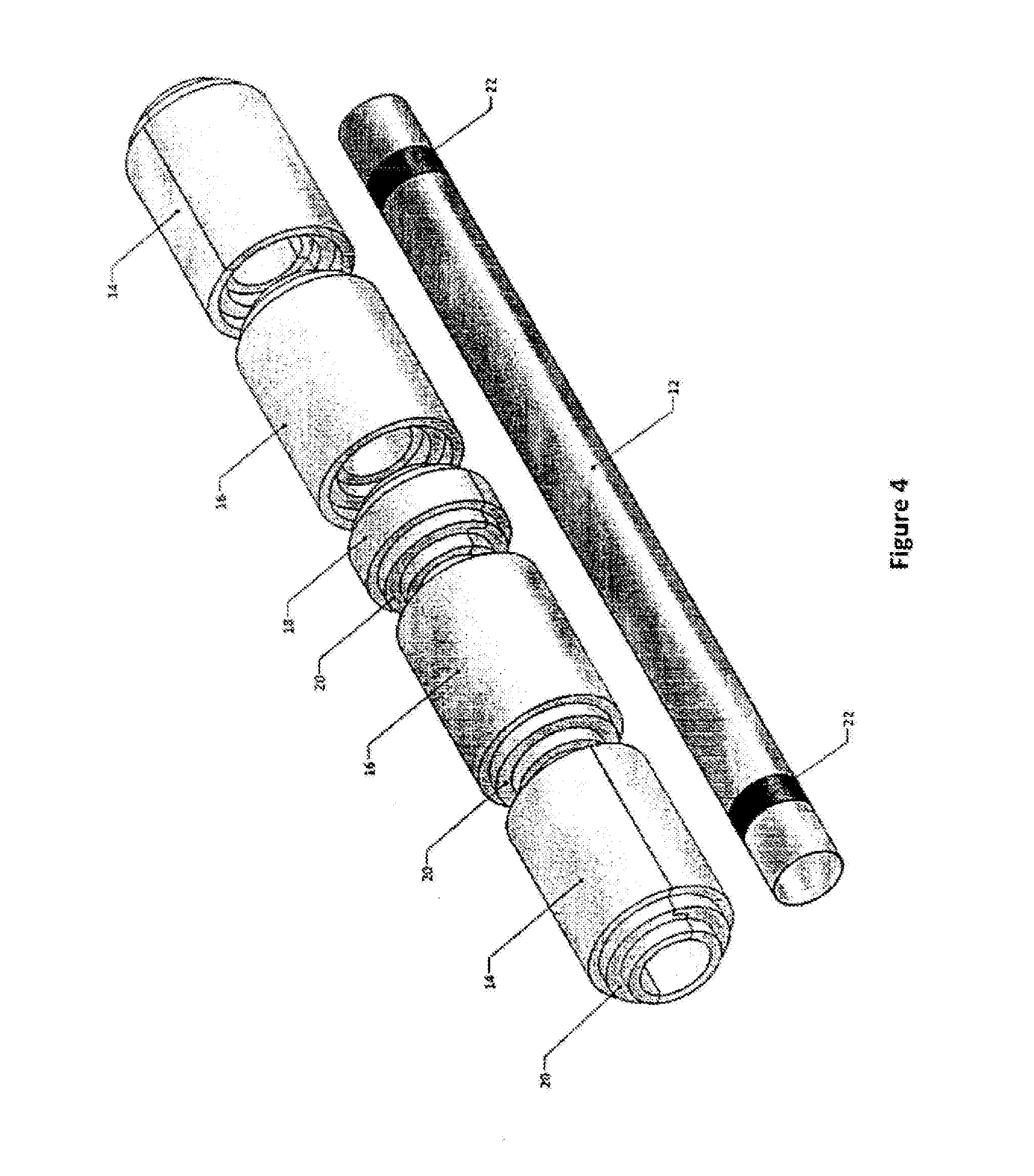
[0077]In FIGS. 1 through 9 there is shown an insulation system in accordance with the present invention for insulation of fluid storage and transfer systems in the form of a prefabricated insulation system comprising a layer of preformed low density polyurethane foam 10. The preformed low density polyurethane foam 10 is provisded in the form of CETRAFOAM® from Cetra Technologies Ply Ltd. CETRAFOAM® is a 50 kg / m3 rigid, closed cell, HCFC free PUR / PIR foam. As seen in FIG. 1, the insulation system is cylindrical and is adapted to encase at least a portion of a pipe 12. As shown in FIG. 4, the insulation system comprises a number of complimentary moulded cylinders of varying lengths 14, 16 and 18.

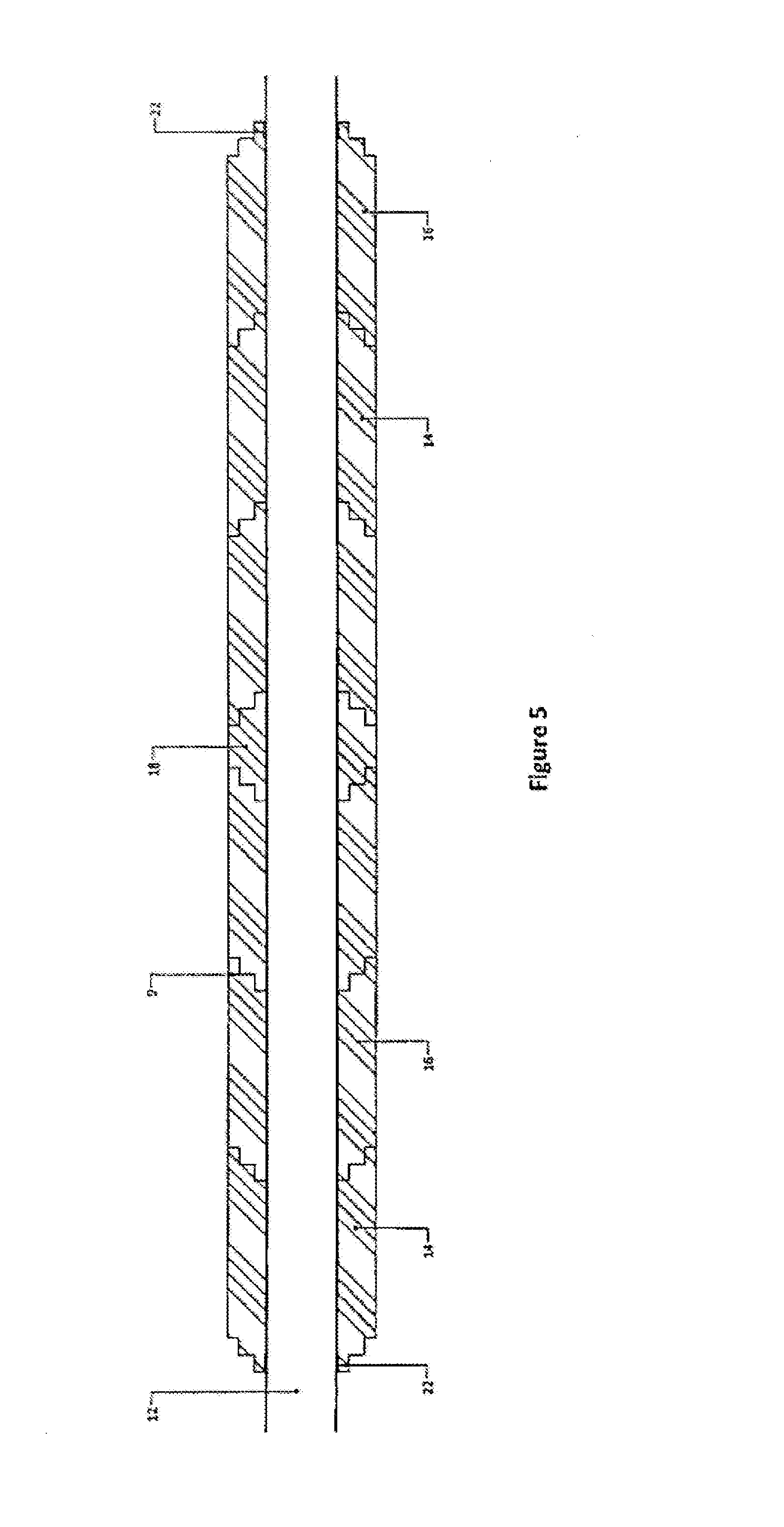
[0078]Shiplap joints 20 are provided longitudinally and at each circumferential end of the moulded cylinders 14, 16 and 18 for mating with an adjacent cylinders, best seen in FIGS. 2, 3 and 4.

[0079]FIGS. 4 and 5 depict an arrangement with cylinders 14 and 16 placed over the pipe 12 and makeup ...

second embodiment

[0087]In FIGS. 10 and 11, there is shown an insulation system in accordance with the present invention. Like numerals in FIGS. 10 and 11 denote like parts in FIGS. 1 to 9.

[0088]As shown in FIG. 10, the moulded cylinder 14 is provided as two complimentary half-pipes 50. Complimentary half-pipes 50 are thermally sealed longitudinally 52 and circumferentially 54 with cryogenic insulation material such as solvent free, high strength, thermosetting two component urethane adhesive.


PUM

PropertyMeasurementUnit
Tensile modulusaaaaaaaaaa

Abstract

An insulation system comprising low density foam with a tensile modulus less than 5 MPa at ambient conditions and less than 10 MPa under cryogenic service conditions.

Description

TECHNICAL FIELD[0001]The present invention relates to an insulation system. More particularly, the insulation system of the present invention is adapted to clad and insulate fluid transport and storage systems.BACKGROUND ART[0002]The following discussion of the background art is intended to facilitate an understanding of the present invention only. The discussion is not an acknowledgement or admission that any of the material referred to is or was part of the common general knowledge as at the priority date of the application.[0003]Insulation cladding for pipes operating at low temperatures typically uses low density polyurethane / polyisocyanurate foam and or cellular glass sections. Typical applications for such pipe cladding are where the process pipework is required to operate at temperatures below 100° C. High quality insulation systems currently being used in deep cryogenic service to −200° C. consist of layers of prefabricated sections that are assembled piecemeal onto the pipe...

Claims


Application Information

Patent Timeline
IPC IPC(8): F16L59/14F16L59/02
CPCF16L59/029F16L59/14F16L59/141B32B5/18B32B7/14B32B1/08B32B2262/101B32B2266/0278B32B2266/08B32B2307/304B32B2307/54B32B2307/7246B32B2597/00C09J175/04C08G2101/00
Inventor CHALLENOR, HARRILL ASHLEY
Owner CHALLENOR HARRILL ASHLEY
Why Eureka
Try Eureka