Eye gaze imaging

a technology of eye gaze and eye detection, applied in the field of eye gaze imaging, can solve the problems of difficult implementation, large device size, difficult to accurately determine eye gaze, etc., and achieve the effect of sufficient eye gaze tracking accuracy and robustness

Active Publication Date: 2016-06-16
SMART EYE
View PDF1 Cites 19 Cited by
  • Summary
  • Abstract
  • Description
  • Claims
  • Application Information

AI Technical Summary

Benefits of technology

[0006]It is an object of the present invention to address the shortcomings of the prior art, and to provide an eye gaze tracking device which is as compact as possible. Another object of the invention is to maintain a sufficient eye gaze tracking accuracy and robustness.

Problems solved by technology

Using only one camera, it is sometime difficult to correctly determine the eye gaze.
Such a device becomes relatively bulky, and is difficult to implement in a space restricted environment, such as an automobile.

Method used


Image

  • Eye gaze imaging
  • Eye gaze imaging
  • Eye gaze imaging

Examples


Embodiment Construction

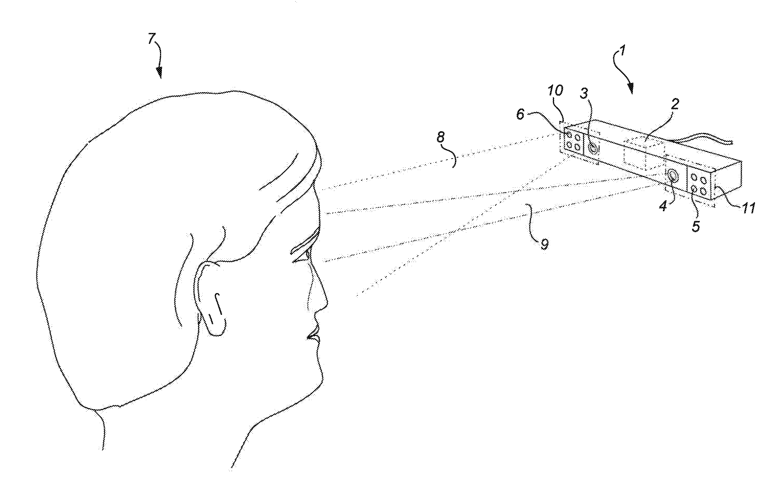
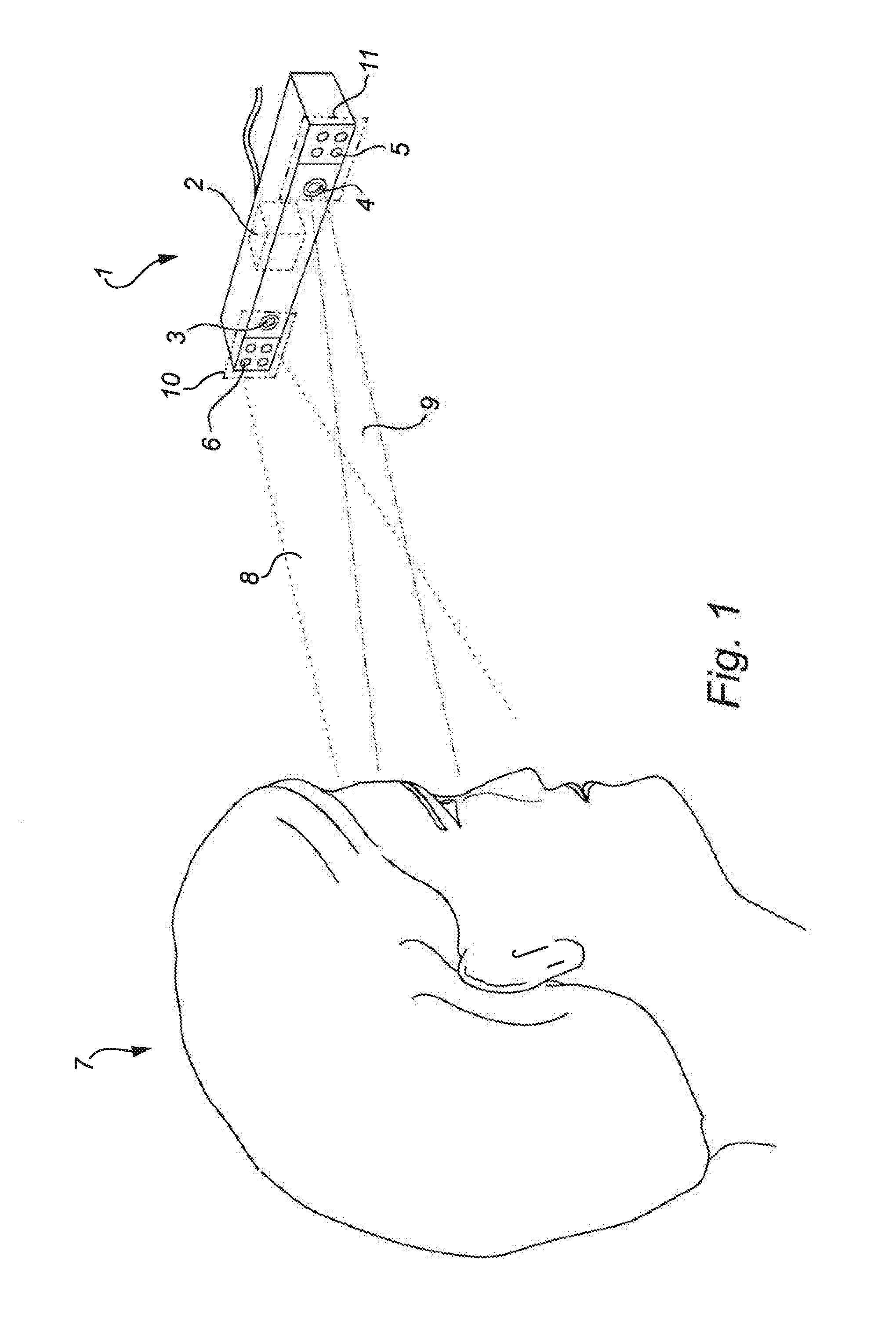
[0033]FIG. 1 shows a device 1 for acquiring a combined eye gaze image of an object 7 according to an embodiment of the present invention. The device is especially adapted for detection and analysis of eye gaze in dark-eye effect conditions. A device according to the invention may be implemented in many types of applications, such as integrated in a vehicle dashboard or at the screen of a personal computer. However, in the illustrated case the device 1 is shown directed at an object 7 without an application context. The device 1 comprises a control unit 2, a first camera 3, a second camera 4, a first light source 6 and a second light source 5. The first camera 3 and the second camera 4 are preferably electronic image sensor cameras, either of snapshot type or delivering a stream of consecutive images. The images can be in a digital format, e.g. a bitmap format, or in analog form which then can be converted to a digital format, e.g. using a framegrabber circuit (not shown). In the ill...


PUM


Abstract

A device for acquiring a combined eye gaze image of an object under dark-eye effect conditions, with a first camera, a second camera, a first light source and a second light source being located on opposite sides of, and on essentially equal distance to a central optical axis. A control unit is arranged to acquire the combined eye gaze image by capturing, in a first point in time, a first frame of the object with the first camera with the second light source activated, and, at a second point in time, capturing a second frame of the object with the second camera with the first light source activated. The device comprises no additional light sources further away from the central optical axis than the first location and the second location. The device is thereby designed as compact as possible while a sufficient eye gaze tracking accuracy and robustness is maintained.

Description

FIELD OF THE INVENTION[0001]The present invention relates to a device for illuminating, imaging and detecting the eye, for example relative position of eyelids, the position of the eyes and the gaze direction.BACKGROUND OF THE INVENTION[0002]For several applications in for example the technical fields of driver analysis in vehicles and user control of personal computers there is a need to acquire information on the users' eye gaze direction, the movements of the eyes and the eyelids and the position of the user. Among possible methods to image and analyze the users eyes there is a group of methods based on detecting reflections on the cornea. Knowledge of the interrelationship between the imaging system and the light source that is reflected in the pupil enables calculation of the eye gaze direction. Using only one camera, it is sometime difficult to correctly determine the eye gaze. This may be solved by using two or more light sources, movable light sources or more than one camera...

Claims


Application Information

Patent Timeline
Patent Type & Authority Applications(United States)
IPC IPC(8): G06F3/01G06K9/00A61B3/113
CPCG06F3/013G06K9/00604A61B3/113G06V40/19
Inventor RYDBERG, MARTINKRANTZ, MARTIN
Owner SMART EYE
Why Eureka
Try Eureka