Signaling and controlling a power grid coupling actuators

a technology of power grid coupling actuator and actuator, which is applied in the direction of ac network voltage adjustment, air break switch, relay, etc., can solve the problems of difficult coordination of control and communication, weaker small generators than large power generators, and difficult control of power grid actuators with high penetration. , to achieve the effect of decentralized control

Active Publication Date: 2016-06-16
SIEMENS AG
View PDF10 Cites 2 Cited by
  • Summary
  • Abstract
  • Description
  • Claims
  • Application Information

AI Technical Summary

Benefits of technology

[0010]As a result, a decentralized control is advantageously possible. Therefore, no extra central control unit is needed.
[0011]Furthermore, no topology information is needed. By generating the control action in dependence on the communication signal, in particular on the amplitude of the communication signal, an optimal use of reactive and / or active in the power grid is possible.

Problems solved by technology

In power grids, like energy distribution grids with high penetration of actuators like renewable energy sources, one challenge is to satisfy a quality requirement for the electricity, especially satisfying voltage limits and overloads of power components, like transformers or power lines.
The control of power grids with high penetration of actuators is challenging because the control paradigm changed from a few large power generators to many local small generators, e.g. voltaic generators, biogas generators or small wind turbines.
Small generators are weaker than large power generators when connected.
Due to the large number of local generators, coordinated control and the required communication are hard to realize.
Obtaining an accurate model, especially for distribution grids that are extensive in dimensions, is expensive and difficult to maintain.
So, conventional load management communication systems cannot be used for signaling voltage problems between actuators in a power grid.

Method used


Image

  • Signaling and controlling a power grid coupling actuators
  • Signaling and controlling a power grid coupling actuators
  • Signaling and controlling a power grid coupling actuators

Examples


Embodiment Construction

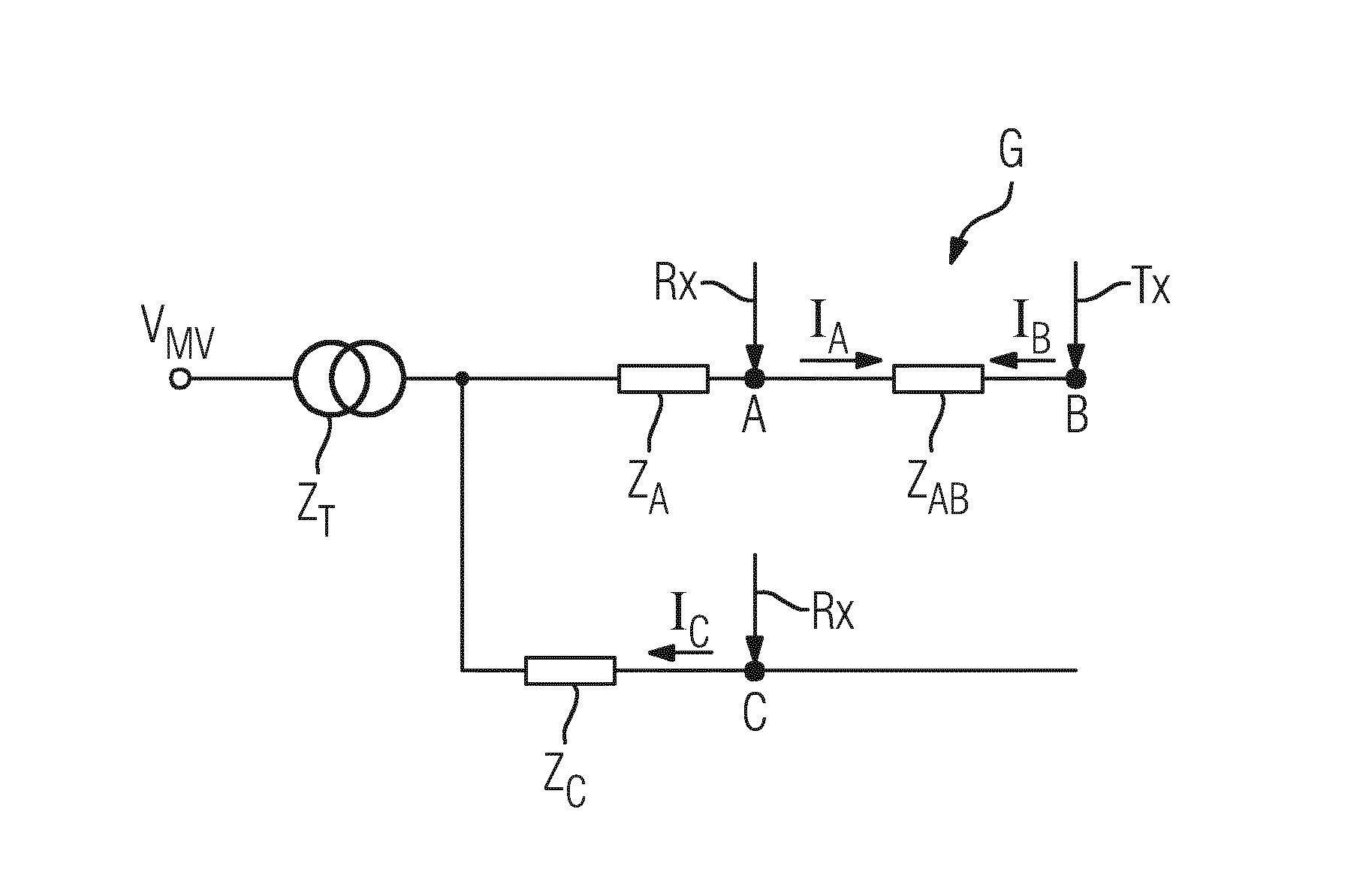
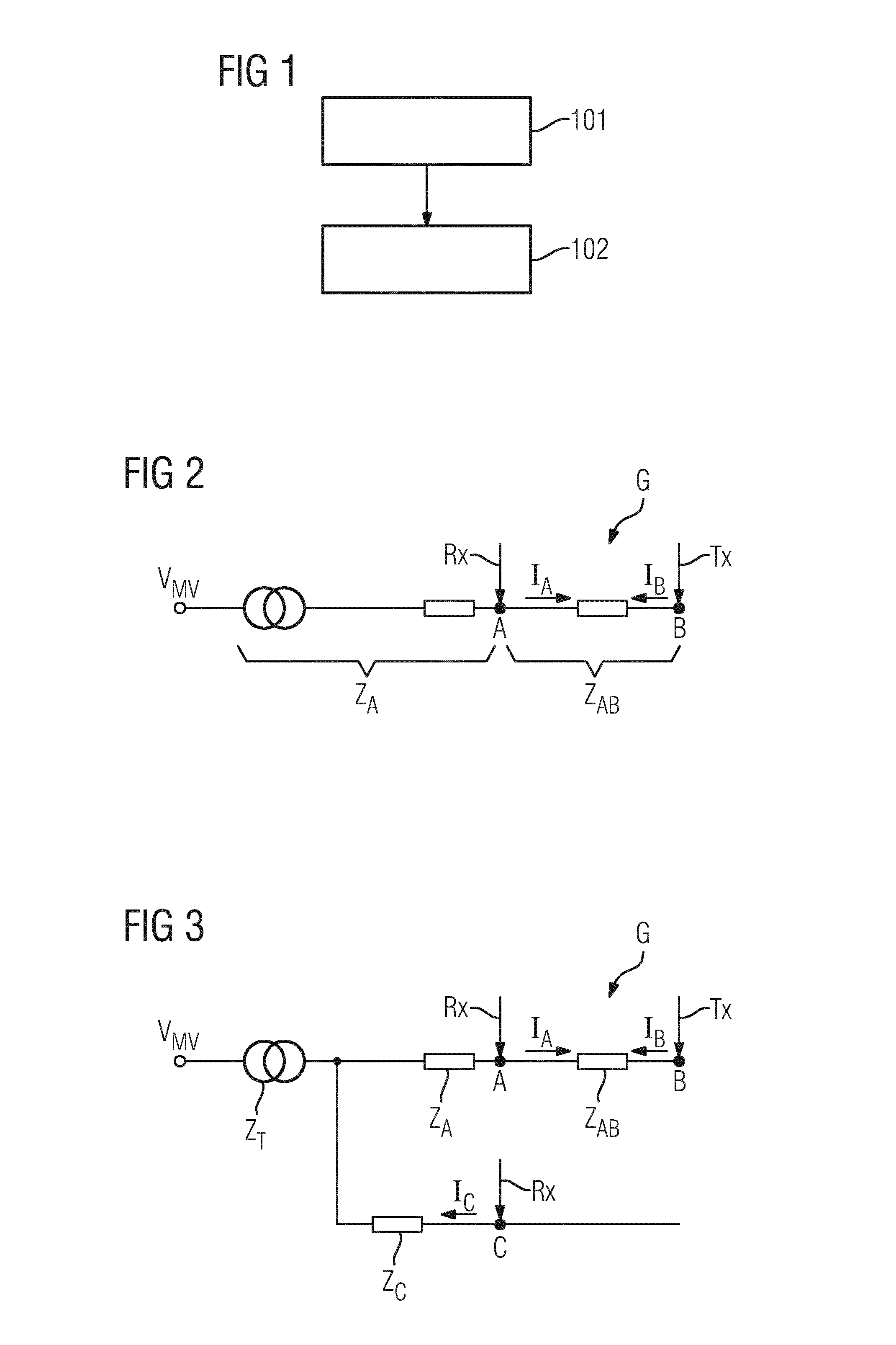
[0064]In FIG. 1, a first embodiment of a sequence of method steps for signaling and controlling in a power grid G (see FIG. 2 or 3) coupling a plurality of actuators A, B, C for providing power signals is depicted.

[0065]In act 101, at the actuator B of the actuators A, B, C, a voltage problem is detected. In case that a voltage problem is detected, a communication signal IB based on the detected voltage problem is generated at the actuator B. Then, the generated communication signal IB is transmitted over the power grid G by the actuator B. FIGS. 2 and 3 illustrate simple representations of the power grid G. In FIGS. 2, 3, Tx indicates the transmitting node, here B, where Rx indicates the receiving node, in FIG. 2 node or actuator A, and in FIG. 3 nodes or actuators A, C.

[0066]In the examples of FIGS. 2 and 3, the actuator B may be also called transmitting (TX) actuator or first actuator, and the actuators A and C may be also called receiving (RX) or second actuators.

[0067]For examp...


PUM


Abstract

A method for signaling and controlling in a power grid coupling a plurality of actuators for providing power signals is provided. At a first actuator, a voltage problem is detected, a communication signal is generated based on the detected voltage problem, and the generated communication signal is transmitted over the power grid. At a second actuator, the transmitted communication signal is received, a control action is generated based on the received communication signal and the generated control action is transmitted over the power grid towards the first actuator.

Description

CROSS-REFERENCE TO RELATED APPLICATION[0001]This application is the National Stage of International Application No. PCT / EP2013 / 065744, filed on Jul. 25, 2013, the entire content of which is hereby incorporated by reference in its entirety.FIELD[0002]The disclosed embodiments relates to a method and to a device for signaling and controlling a power grid coupling a plurality of actuators for providing power signals.BACKGROUND[0003]In power grids, like energy distribution grids with high penetration of actuators like renewable energy sources, one challenge is to satisfy a quality requirement for the electricity, especially satisfying voltage limits and overloads of power components, like transformers or power lines.[0004]The control of power grids with high penetration of actuators is challenging because the control paradigm changed from a few large power generators to many local small generators, e.g. voltaic generators, biogas generators or small wind turbines. Small generators are w...

Claims


Application Information

Patent Timeline
Patent Type & Authority Applications(United States)
IPC IPC(8): H02J3/12H02J13/00H02J3/38
CPCH02J3/12H02J3/383H02J13/002H02J3/387H02J3/386H02J3/381Y04S40/121H02J13/00007Y02E10/56Y02E10/76Y02E60/00Y04S10/12Y02E40/70
Inventor BUHL, MICHAEL BERNHARDMETZGER, MICHAELNIELEBOCK, SEBASTIANSOLLACHER, RUDOLFSZABO, ANDREI
Owner SIEMENS AG
Why Eureka
Try Eureka