Clock generator and method of adjusting phases of multiphase clocks by the same

a clock generator and multi-phase clock technology, applied in the field of clock generators, can solve the problems of increasing the difficulty of using a full-rate single-phase clock for high-speed transmission lines, increasing the speed, and the inability of conventional circuits to independently adjust the phases and frequencies, so as to accurately control the phases of multi-phase clocks. , the effect of accurately controlling the phases of multi-phase clocks

Active Publication Date: 2016-06-16
MEGACHIPS
View PDF3 Cites 8 Cited by
  • Summary
  • Abstract
  • Description
  • Claims
  • Application Information

AI Technical Summary

Benefits of technology

[0027]According to the present invention, the clock generator can accurately control the phases of the multiphase clocks while maintaining the frequencies of the multiphase clocks constant.
[0028]According to the present invention, the clock generator can accurately control the phases of the multiphase clocks without being affected by the manufacturing variations.

Problems solved by technology

The difficulty in using a full-rate single-phase clock for high-speed transmission lines has been increasing along with the increase in the speed of the clocks in recent years, and the role played by the multiphase clocks is important.
Therefore, the conventional circuit cannot independently adjust the phases and the frequencies.
Particularly, even if the conventional circuit controls the phases of the multiphase clocks, the conventional circuit cannot maintain the frequencies of the multiphase clocks constant.
Therefore, accurate control is difficult in a semiconductor integrated circuit that operates at a significantly high speed.

Method used


Image

  • Clock generator and method of adjusting phases of multiphase clocks by the same
  • Clock generator and method of adjusting phases of multiphase clocks by the same
  • Clock generator and method of adjusting phases of multiphase clocks by the same

Examples


Embodiment Construction

[0042]Embodiments of the present invention will now be described with reference to the drawings.

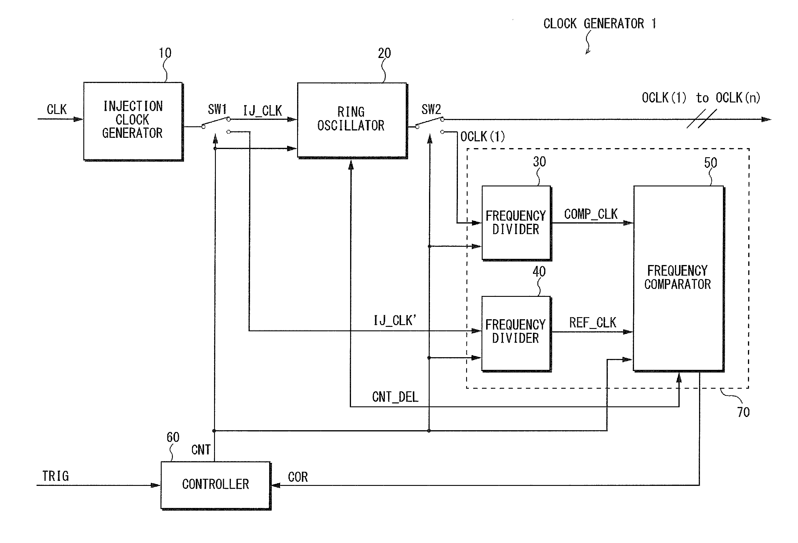
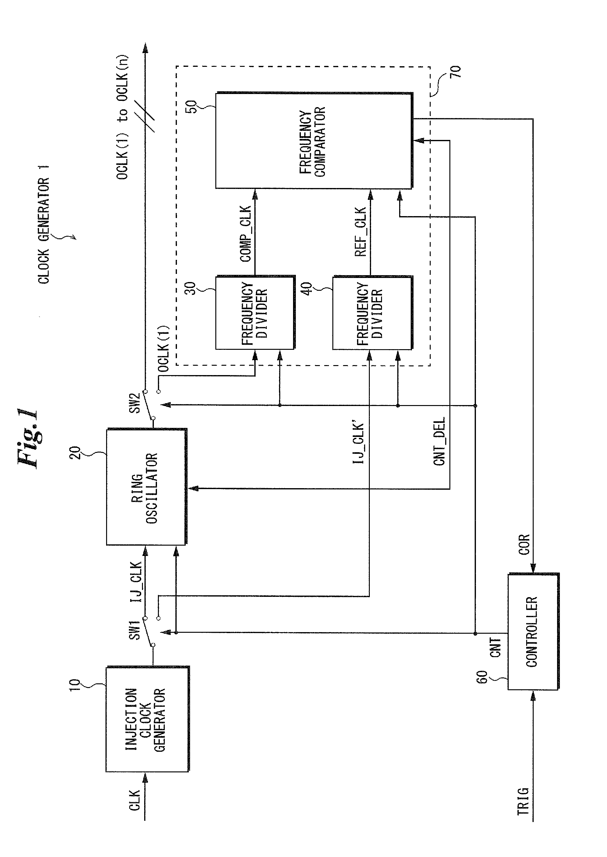
[0043]FIG. 1 is a block diagram showing an example of a schematic configuration of a clock generator according to an embodiment of the present invention. As shown in FIG. 1, a clock generator 1 according to the present embodiment may be configured to include, for example, an injection clock generator 10, switches SW1 and SW2, a multiphase oscillator (ring oscillator) 20, frequency dividers 30 and 40, a frequency comparator 50, and a controller 60.

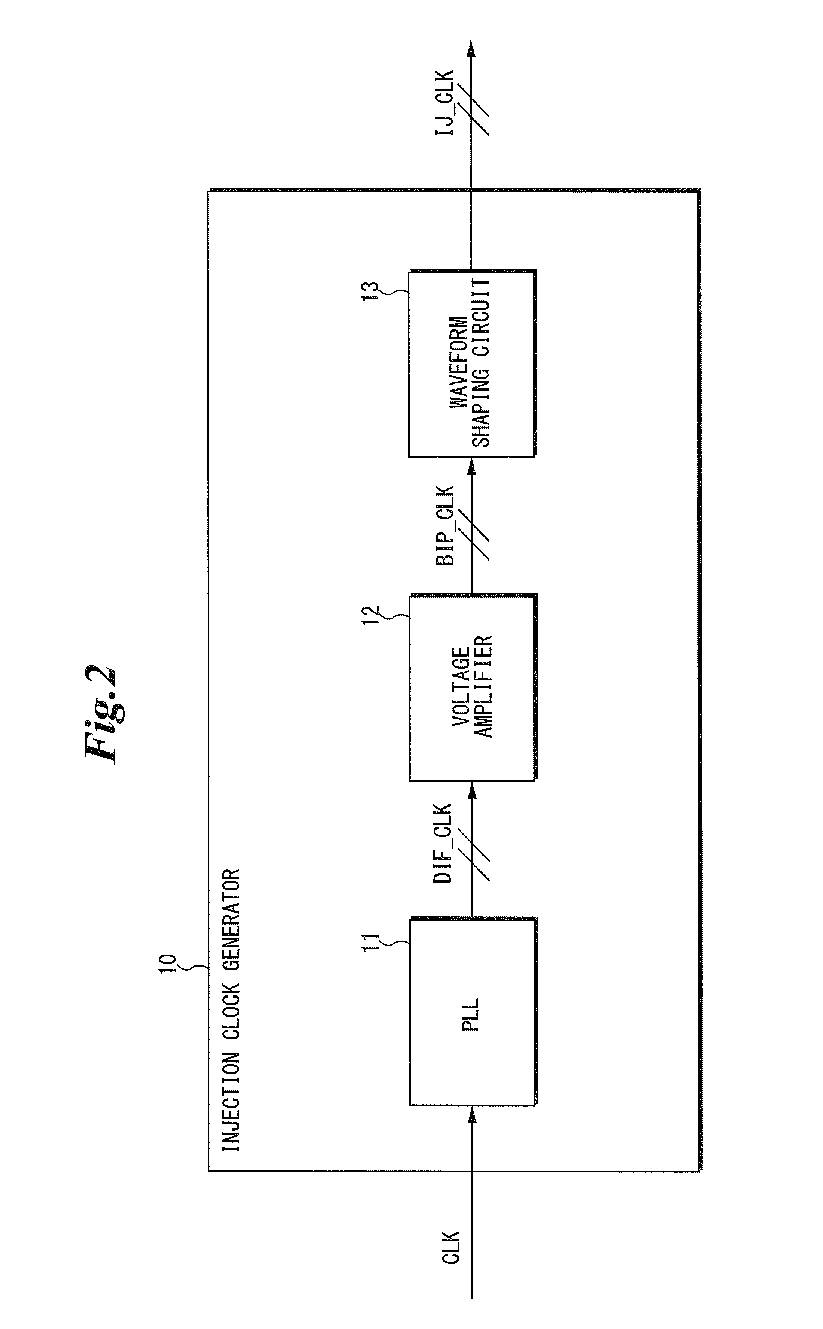
[0044]The injection clock generator 10 may generate a two-phase injection clock IJ_CLK based on a system clock CLK. Specifically, the injection clock generator 10 may generate the two-phase injection clock IJ_CLK based on the system clock CLK and output either the clock to the ring oscillator 20 or the frequency divider 40 through the switch SW1.

[0045]The switch SW1 may switch an output destination of the injection clock IJ_CLK output from the in...


PUM


Abstract

A clock generator that outputs multiphase clocks comprises a ring oscillator that includes a plurality of inverter circuits connected in a circular pattern and outputs, from the inverter circuits, clocks provided with a delay time based on a delay control signal, a first frequency divider that divides an injection clock by a first value and outputs the clock as a reference clock, a second frequency divider that divides one of the multiphase clocks by a second value and outputs the clock as a comparison clock, and a frequency comparator that compares frequencies of the reference clock and the comparison clock and output the delay control signal based on a result of the comparison. The ring oscillator is configured to adjust the delay time based on the delay control signal.

Description

FIELD OF THE INVENTION[0001]The present invention generally relates to a clock generator, and particularly, to a clock generator that outputs multiphase clocks.BACKGROUND OF THE INVENTION[0002]Conventionally, since multiphase clocks allow of accurate adjustment of a phase difference between clocks, and thus are generally used in semiconductor integrated circuits with high-speed transmission lines. The difficulty in using a full-rate single-phase clock for high-speed transmission lines has been increasing along with the increase in the speed of the clocks in recent years, and the role played by the multiphase clocks is important.[0003]A ring oscillator is known as an example of a multiphase oscillator that generates multiphase clocks. The ring oscillator includes a plurality of inverter circuits circularly-connected. The ring oscillator oscillates at a frequency based on the delay time of the clock in each inverter circuit and based on the drive capability of the power that drives th...

Claims


Application Information

Patent Timeline
Patent Type & Authority Applications(United States)
IPC IPC(8): H03K5/15H03K3/03
CPCH03K3/0315H03K5/15013H03K5/15026
Inventor TANIHIRA, IZUHO
Owner MEGACHIPS
Why Eureka
Try Eureka