Aerofoil blade or vane

a technology of aerofoil and blades, which is applied in the direction of liquid fuel engines, vessel construction, marine propulsion, etc., can solve the problems of un-cooled turbine life falling, cooling air from the compressor that is used to cool the hot turbine components is not used fully to extract work from the turbine, and the cooling effect of coolant is least effective, so as to achieve the effect of maximising the area available for the reverse-pass coolant passages

Active Publication Date: 2016-06-23
ROLLS ROYCE PLC
View PDF10 Cites 30 Cited by
  • Summary
  • Abstract
  • Description
  • Claims
  • Application Information

AI Technical Summary

Benefits of technology

[0021]The aerofoil blade or vane can further comprise at least one aerofoil coolant inlet at one of its lateral edges. Inlets at both edges can allow for more equal coolant distribution, but in some cases it can be desirable to only have one inlet.
[0022]The aerofoil blade or vane can further comprise an internal pressure-side plenum that is connected to the aerofoil coolant inlet, and which is further connected to the first reverse-pass coolant passage, or first and second reverse-pass passages, via a cooling passage inlet. The internal plenum can allow for the collection and distribution of the coolant without taking up space at the suction side, thereby maximising the area available for the reverse-pass coolant passages. The plenum can also allow for coolant to be used for pressure-side cooling before before being directed to the suction side.
[0023]The cooling passage inlet can be an impingement plate. The internal pressure-side plenum can extend across 50% or more of the pressure-side surface, optionally 60% or more, further optionally 70% or more, further optionally 80% or more, and still further optionally 90% or more. The inlet can be positioned at 60% or greater along the streamwise surface distance on the suction side, optionally at 70% or greater, further optionally at 80% or greater, and still further optionally at 90% or greater. In this way, the reverse-pass coolant passages can extend along a significant portion of the suction side surface, whilst any directly-fed ‘normal’ flow passages will provide the greatest cooling benefit to the trailing edge.

Problems solved by technology

However as turbine entry temperatures increase, the life of an un-cooled turbine falls, necessitating the development of better materials and the introduction of internal air cooling.
Cooling air from the compressor that is used to cool the hot turbine components is not used fully to extract work from the turbine.
Therefore, as extracting coolant flow has an adverse effect on the engine operating efficiency, it is important to use the cooling air effectively.
Some of the cooling air, however, can leave through film cooling holes formed in the suction side and pressure side walls.
Therefore, the coolant is least effective where cooling is needed most: in the trailing-edge overhang region.

Method used


Image

  • Aerofoil blade or vane
  • Aerofoil blade or vane
  • Aerofoil blade or vane

Examples


Embodiment Construction

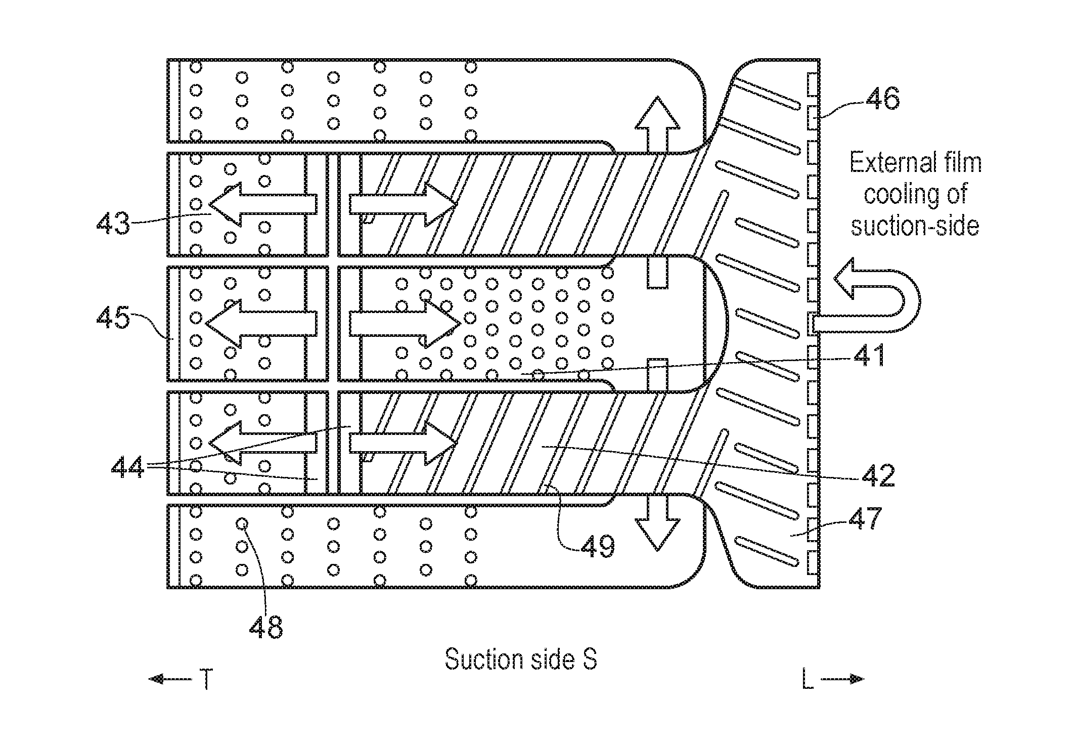
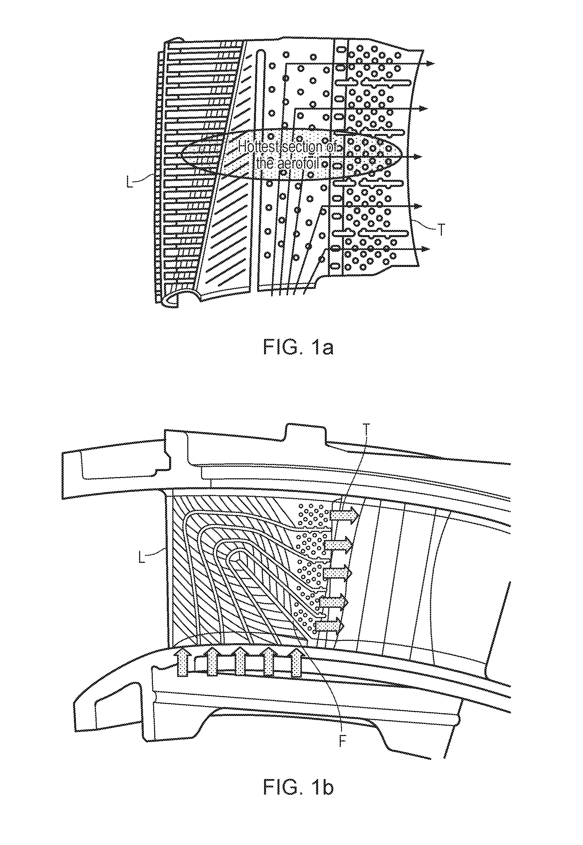
[0048]Internal cooling designs for aerofoils, such as for a blade or vane for a turbine of a gas turbine engine, are presented below. Each design incorporates a significant amount of ‘reverse-pass’ coolant flow (i.e. coolant inside the aerofoil that flows from the trailing-edge towards leading-edge, which is in the opposite direction to the mainstream flow outside the aerofoil). That reverse-pass coolant flow is preferably on the suction-side wall of the aerofoil. There are significant advantages associated with these reverse-pass systems, including (a) improved cooling efficiency, i.e. less coolant is needed to achieve cooling to the same maximum wall temperature, or a smaller maximum wall temperature is achieved for the same amount of coolant, and (b) more uniform wall temperatures in the axial direction, which in turn reduces thermal stresses. The designs presented seek to maximise the number and / or length of reverse-pass portions, whilst satisfying manufacturability and pressure...


PUM


Abstract

An aerofoil blade or vane for the turbine of a gas turbine engine includes: an aerofoil leading edge; an aerofoil trailing edge; an aerofoil suction side; and at least one reverse-pass coolant passage, extending within the aerofoil blade or vane; wherein the at least one reverse-pass coolant passage includes a substantial reverse-pass portion in which, in use, coolant flows in a direction away from the trailing edge and towards the leading edge.

Description

TECHNICAL FIELD OF INVENTION[0001]The present invention relates to an aerofoil blade or aerofoil vane for the turbine of a gas turbine engine. In particular, the invention relates to how such blades or vanes are cooled.BACKGROUND OF INVENTION[0002]The performance of gas turbine engines, whether measured in terms of efficiency or specific output, is improved by increasing the turbine gas temperature. It is therefore desirable to operate the turbines at the highest possible temperatures. For any engine cycle compression ratio or bypass ratio, increasing the turbine entry gas temperature produces more specific thrust (e.g. engine thrust per unit of air mass flow). However as turbine entry temperatures increase, the life of an un-cooled turbine falls, necessitating the development of better materials and the introduction of internal air cooling.[0003]In modern engines, the high-pressure turbine gas temperatures are hotter than the melting point of the material of the blades and vanes, n...

Claims


Application Information

Patent Timeline
Patent Type & Authority Applications(United States)
IPC IPC(8): F01D5/18F01D25/12F01D9/04
CPCF01D5/187F01D9/041F01D5/186F01D25/12F05D2260/201F05D2240/306F05D2240/124F05D2260/202F05D2220/32
Inventor KIROLLOS, BENJAMINPOVEY, THOMAS
Owner ROLLS ROYCE PLC
Why Eureka
Try Eureka