Hydraulic system for an automatic transmission

a technology of automatic transmission and hydraulic system, which is applied in the direction of fluid-actuated clutches, non-mechanical actuated clutches, clutches, etc., can solve the problems of fuel consumption and co2 emissions, leakage losses at sealing points, and malfunctions that block the drive train, so as to reduce the control pressure

Active Publication Date: 2016-06-23
ZF FRIEDRICHSHAFEN AG
View PDF4 Cites 8 Cited by
  • Summary
  • Abstract
  • Description
  • Claims
  • Application Information

AI Technical Summary

Benefits of technology

[0015]The hydraulic system is formed in an arrangement such that the locking device comprises at least one locking piston, which is arranged in a displaceable manner in a locking piston bore and, by means of being subjected to the control pressure, is displaceable from a locked position into the locked position, and is held in the locked position by the control pressure. Since the closure device is moved, by means of the control pressure, from the open position into the closed position, it serves to simplify the hydraulic system, and to hydraulically undertake the actuation of the locking device. Thus, the pressure to be generated by the transmission pump must only be so high in order to hold the locking piston in the locked position. Advantageously, through this drop in pressure, a strong reduction in the power consumption of the transmission pump is possible.
[0034]It is possible that an automatic transmission that comprises a shaft and a clutch hub features a stop valve arranged with an annular piston, whereas the annular piston is arranged concentrically to a shaft axis of the shaft around the latter, and is arranged radially inside the clutch hub that is likewise arranged concentrically to the shaft. Thereby, a space-saving arrangement of a stop valve is also possible.

Problems solved by technology

The energy to generate pressure by means of the hydraulic pump must be applied by the engine of the motor vehicle, which has effects on fuel consumption and CO2 emissions.
In addition, leakage losses arise at sealing points, such as pressure oil supply lines from the transmission housing through so-called “rotary oil supply lines,” which are sealed by means of gap seals, such as slide bearings and / or rectangular rings, in the rotating transmission shaft.
In terms of functional reliability, it is thereby disadvantageous that the stop valve, and thus the relevant shifting element, can no longer be opened upon the stop or failure of the engine or the pump, and thus a lack of pressurization of the automatic transmission, such that a malfunction that blocks the drive train may arise.
However, in a disadvantageous manner, the stop valve must be constantly subjected to a control pressure in order to keep it closed.
However, the limit of the reduction of the surfaces is specified by a minimum value of the flow cross-section of the channels closed by means of the balls, below which the shifting element is not able to be filled quickly enough.
Thereby, it is possible to further lower the control pressure for closing the stop valve and thus the power consumption of the pump.

Method used


Image

  • Hydraulic system for an automatic transmission
  • Hydraulic system for an automatic transmission
  • Hydraulic system for an automatic transmission

Examples


Embodiment Construction

[0043]Reference will now be made to embodiments of the invention, one or more examples of which are shown in the drawings. Each embodiment is provided by way of explanation of the invention, and not as a limitation of the invention. For example features illustrated or described as part of one embodiment can be combined with another embodiment to yield still another embodiment. It is intended that the present invention include these and other modifications and variations to the embodiments described herein.

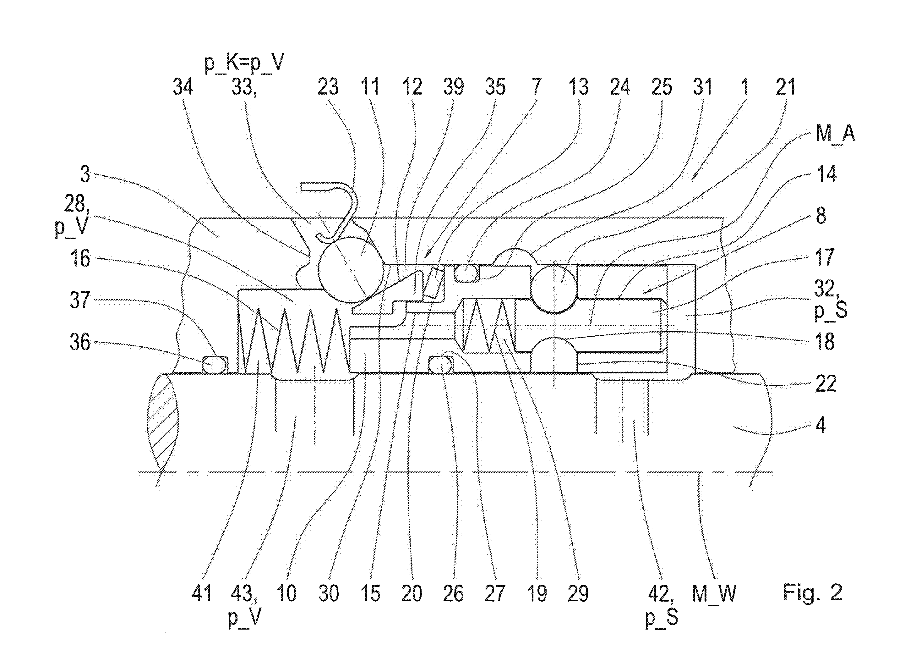
[0044]FIG. 1 shows a partial section through a transmission, whereas, in the partial section, a hydraulically actuated clutch 5, a shaft 4, a clutch hub 103 and a stop valve 101 according to the state of the art are shown. In the partial section, based on the essentially rotationally symmetrical design of the arrangement around a shaft axis M_W, only one half is shown. The clutch 5 comprises a clutch piston 52, a clutch hub 103, a multi-disk pack 54 with outer multi-disks 56 and in...


PUM


Abstract

A hydraulic system for operating an automatic transmission for motor vehicles includes a hydraulic actuator for operating a clutch and a stop valve, whereas the actuator has a pressurizable actuating pressure chamber, which can be closed in a pressure-tight manner by means of the stop valve, such that the clutch pressure is maintained independent of the other pressures of the hydraulic system. The stop valve includes a closure device that is movable by means of a hydraulic control pressure (p_S) into a closed position, in which an actuating pressure chamber port, and thus the actuating pressure chamber, is closed by means of the closure device. The closure device is movable into an open position at least by means of the force of a spring, in which the actuating pressure chamber port is opened. Thereby, the stop valve features a shiftable locking device, by means of which the closure device can be fixed in the closed position.

Description

FIELD OF THE INVENTION[0001]The invention relates to a hydraulic system for an automatic transmission, an automatic transmission, and a method for operating the hydraulic system.BACKGROUND[0002]With automatic transmissions for motor vehicles, such as is known (for example) from DE 10 2005 002 337 A1, the transmission ratio stages are adjusted by means of shifting elements, also referred to as clutches. Clutches may connect two rotatable elements together, and one element connected in a torque-proof manner to the transmission housing to one rotatable element. In the latter case, one also speaks of a brake. Thereby, the shifting elements are formed as frictional-locking multi-disk clutches and positive-locking shifting elements, such as claw couplings. In order to carry out power shifts, i.e. a change to the transmission ratio without an interruption of the pulling force, at least one part of the shifting elements must be formed as frictional-locking shifting elements.[0003]With known...

Claims


Application Information

Patent Timeline
Patent Type & Authority Applications(United States)
IPC IPC(8): F16D48/02
CPCF16D25/14F15B15/26F15B15/261F16D25/0638
Inventor MARGRAF, CHRISTOPHBROM, STEFAN
Owner ZF FRIEDRICHSHAFEN AG
Why Eureka
Try Eureka