
Fully-differential amplification for pyrometry

Active Publication Date: 2016-06-23
ADVANCED ENERGY INDS
View PDF2 Cites 3 Cited by
  • Summary
  • Abstract
  • Description
  • Claims
  • Application Information

AI Technical Summary

Benefits of technology

This patent describes a pyrometer system that uses a differential amplifier circuit to measure optical signals. The system includes a primary photo detector and two transimpedance amplifiers that have different gains and are coupled to the primary photo detector. The system also includes analog to digital converters to transform the output of the amplifiers into digital values. These digital values are then processed by a processor to calculate the temperature or reflectance value of the optical signal. The technical effects of this patent include an improved accuracy and reliability of the pyrometer system and the ability to measure optical signals with high precision.

Problems solved by technology

In manufacturing environments, measuring the temperature of an object without contact has proven to be a complex and daunting task.
Objects in motion are often difficult to touch (e.g., molten sapphire), and objects that are too hot will damage the temperature sensor.
The object of interest also may be easily damaged by contact, thereby precluding measurement of its temperature.
These amplifiers introduce various challenges to optical pyrometry that have yet to be adequately addressed.

Method used


Image

  • Fully-differential amplification for pyrometry
  • Fully-differential amplification for pyrometry
  • Fully-differential amplification for pyrometry

Examples


Embodiment Construction

[0025]The present disclosure relates generally to optical pyrometry. In particular, but not by way of limitation, the present disclosure relates to systems, methods and apparatuses for an improved amplifier for use in optical pyrometry

[0026]The word “exemplary” is used herein to mean “serving as an example, instance, or illustration.” Any embodiment described herein as “exemplary” is not necessarily to be construed as preferred or advantageous over other embodiments.

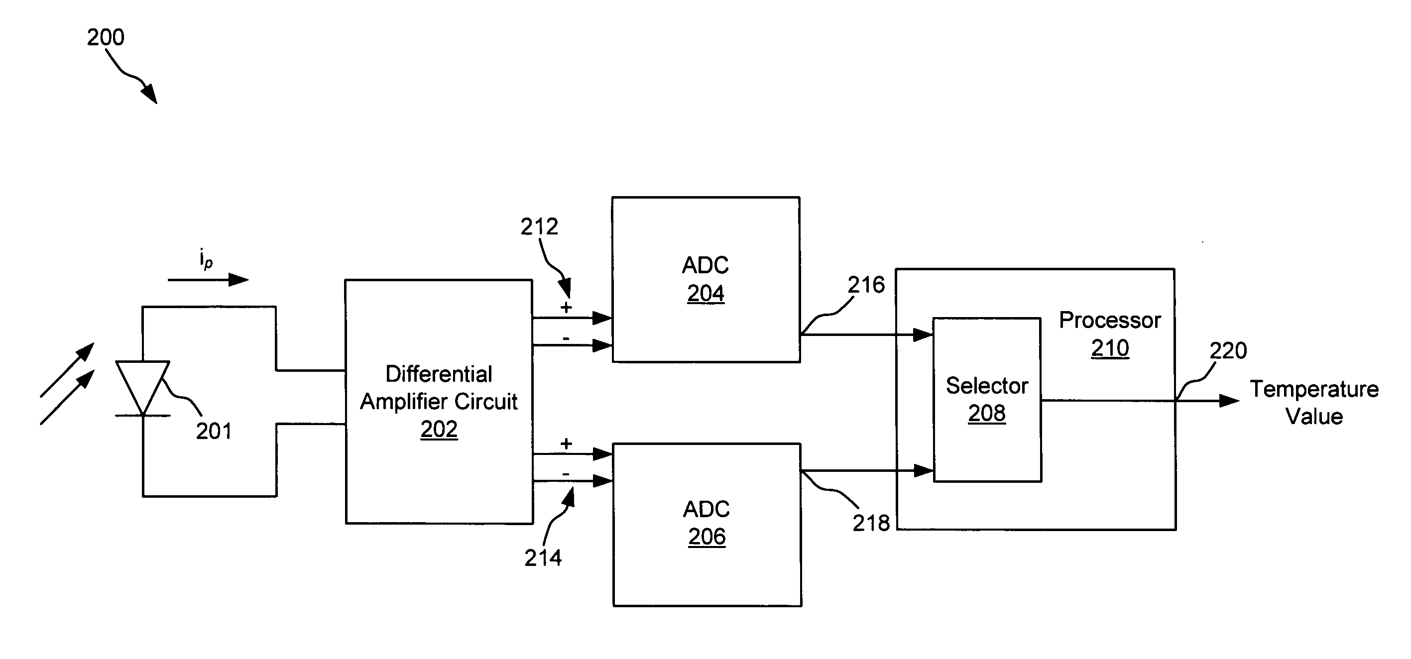
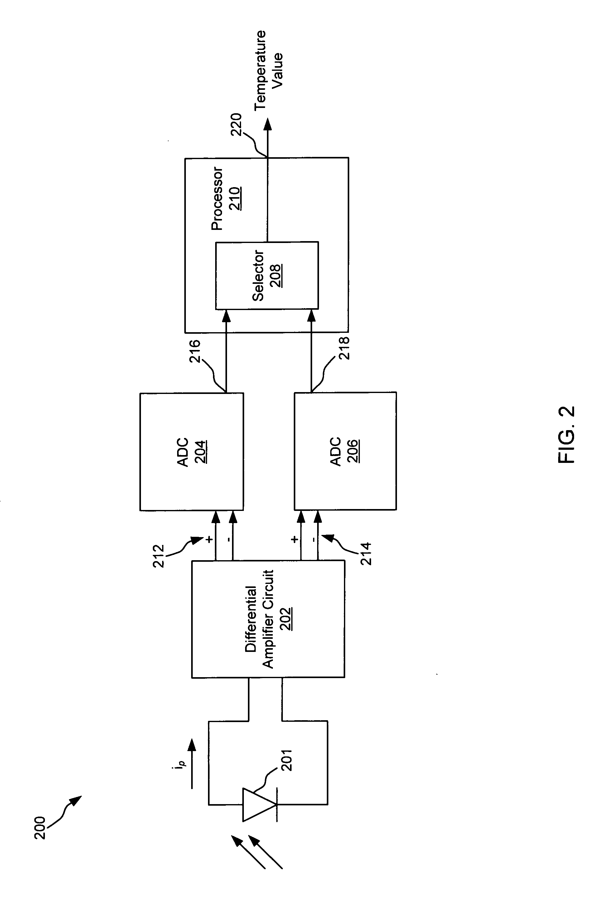
[0027]The term “differential amplifier circuit” is used herein to mean an amplifier having two driven inputs.

[0028]The term “fully differential amplifier circuit” is used herein to mean a type of electronic amplifier that amplifies the difference between two input voltages but suppresses any voltage common to the two inputs. [1] It is an analog circuit with two inputs and one output in which the output is ideally proportional to the difference between the two voltages.

[0029]The term “amplification stage” is used herein t...


PUM


Abstract

This disclosure describes systems, methods, and apparatus for improving the signal-to-noise ratio, increasing sampling speed, and increasing the dynamic range of a pyrometer via improvements to the amplification section. In particular, single-stage non-differentiated amplifiers can be replaced with a differential amplifier circuit that increases gain without a proportional increase in noise. The differential amplifier circuit can comprise a pair of transimpedance amplifier circuits arranged in parallel that receive a differential current from a photo detector and generate a differential voltage output in response having a transconductance gain.

Description

CLAIM OF PRIORITY UNDER 35 U.S.C. §119[0001]The present application for patent claims priority to Provisional Application No. 62 / 096,090 entitled “USE OF A FULLY-DIFFERENTIAL FRONT-END, WITH REVERSE BIAS AND BLIND DETECTION SUPPORT TO ACHIEVE A HIGH-SPEED, LOW NOISE, LOW OFFSET, HIGH-GAIN PYROMETER INTERFACE” filed Dec. 23, 2014, and assigned to the assignee hereof and hereby expressly incorporated by reference herein.FIELD OF THE DISCLOSURE[0002]The present disclosure relates generally to optical pyrometry. In particular, but not by way of limitation, the present disclosure relates to systems, methods and apparatuses for an improved amplifier for use in optical pyrometry.BACKGROUND[0003]In manufacturing environments, measuring the temperature of an object without contact has proven to be a complex and daunting task. Objects in motion are often difficult to touch (e.g., molten sapphire), and objects that are too hot will damage the temperature sensor. The object of interest also may...

Claims


Application Information

Patent Timeline
IPC IPC(8): G01J5/10
CPCG01J5/10G01J1/44G01J5/24G01J2001/4406G01J2001/446H03M1/00
Inventor MURRAY, DONALD F.
Owner ADVANCED ENERGY INDS
Features
  • Generate Ideas
  • Intellectual Property
  • Life Sciences
  • Materials
  • Tech Scout
  • Unparalleled Data Quality
  • Higher Quality Content
  • 60% Fewer Hallucinations
Learn More