
Stator slot temperature sensor and method of manufacturing the same

Active Publication Date: 2016-06-23
DOOSAN HEAVY IND & CONSTR CO LTD
View PDF3 Cites 3 Cited by
  • Summary
  • Abstract
  • Description
  • Claims
  • Application Information

AI Technical Summary

Benefits of technology

The present disclosure tries to solve issues with traditional stator slot temperature sensor assemblies and how they are manufactured. The improvements involve improving the shape of the laminate, using a flexible substrate to mediate connections between lead wires, and changing the angle of the lead wire extended to a drawn out part. These changes provide better accuracy and reliability of the temperature sensor assembly.

Problems solved by technology

The conventional temperature sensor has a problem in that external pressure is applied when the temperature sensor is placed and assembled between the top bar and bottom bar of the stator slot and the external pressure is applied to the element or the lead wire, resulting in disconnection.
Major causes of such disconnection may include disconnection occurring because the structure of the laminate and the resin forming the laminate is inefficient to protect the element or the lead wire, the disconnection of the lead wire generated due to the external pressure if the soldering is excessive, and disconnection attributable to a reduction of mechanical strength occurring because the lead wire extended to the drawn out part is subject to an excessive amount of bending, for example, when the lead wire is bent 90 degrees.

Method used


Image

  • Stator slot temperature sensor and method of manufacturing the same
  • Stator slot temperature sensor and method of manufacturing the same
  • Stator slot temperature sensor and method of manufacturing the same

Examples


Embodiment Construction

[0042]Hereinafter, various embodiments of the present disclosure are described with reference to the accompanying drawings. It should be understood that differences between the embodiments of the present disclosure are not to be taken as a matter of mutually exclusivity. That is, it is to be understood that specific shapes, structures, and characteristics described in this specification may be implemented in other forms in connection with exemplary embodiments without departing from the spirit and scope of the present invention, and the position or arrangement of each element in each disclosed embodiment may be changed. The same or similar reference numerals are used to denote the same or similar elements throughout the drawings. The length, area, thickness, and shape of each element may have been enlarged for convenience sake.

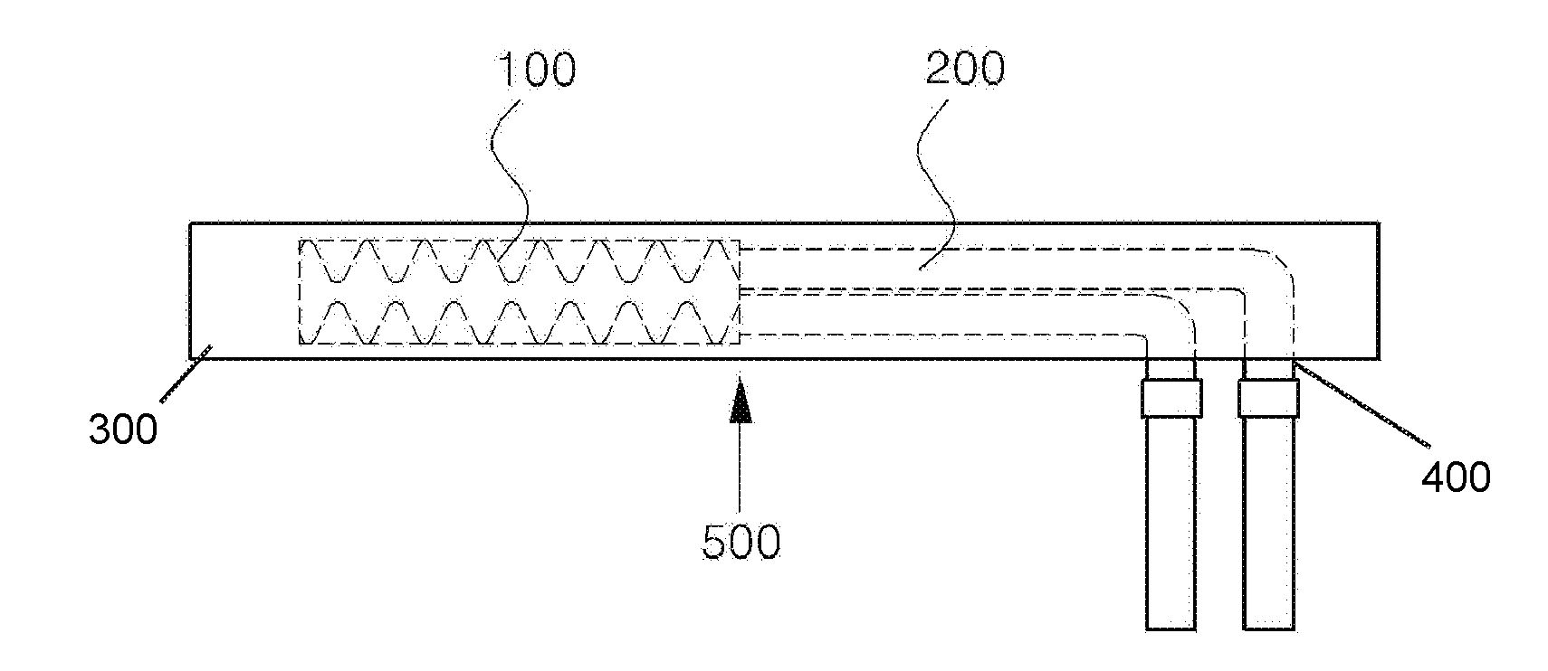
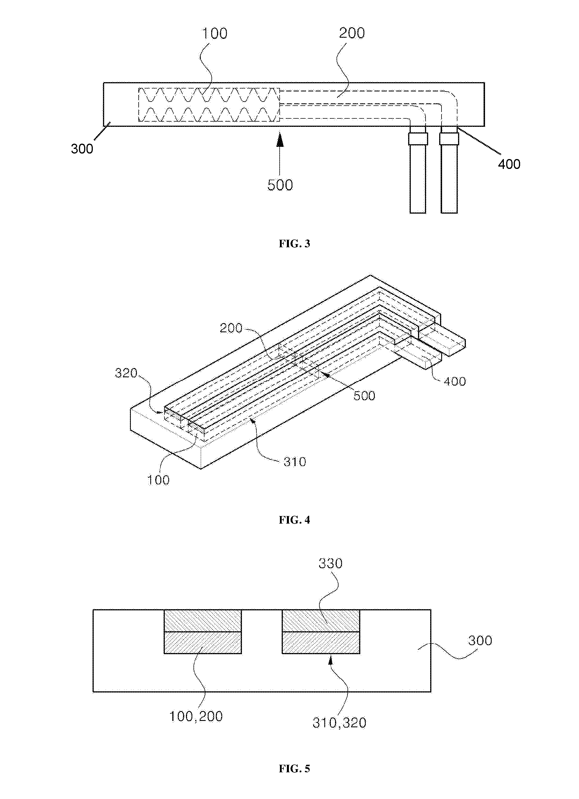
[0043]FIG. 3 is a plan view of a stator slot temperature sensor assembly in accordance with an embodiment of the present disclosure, and FIG. 4 is a perspecti...


PUM


Abstract

Disclosed herein is a temperature sensor assembly. The temperature sensor assembly comprises an element that is a sensing resistor, a pair of parallel lead wires connected to the element, a laminate configured to mechanically protect and surround the element and the lead wires, and lead wire drawn out parts extended and protruded from the lead wires to the outside of the laminate.

Description

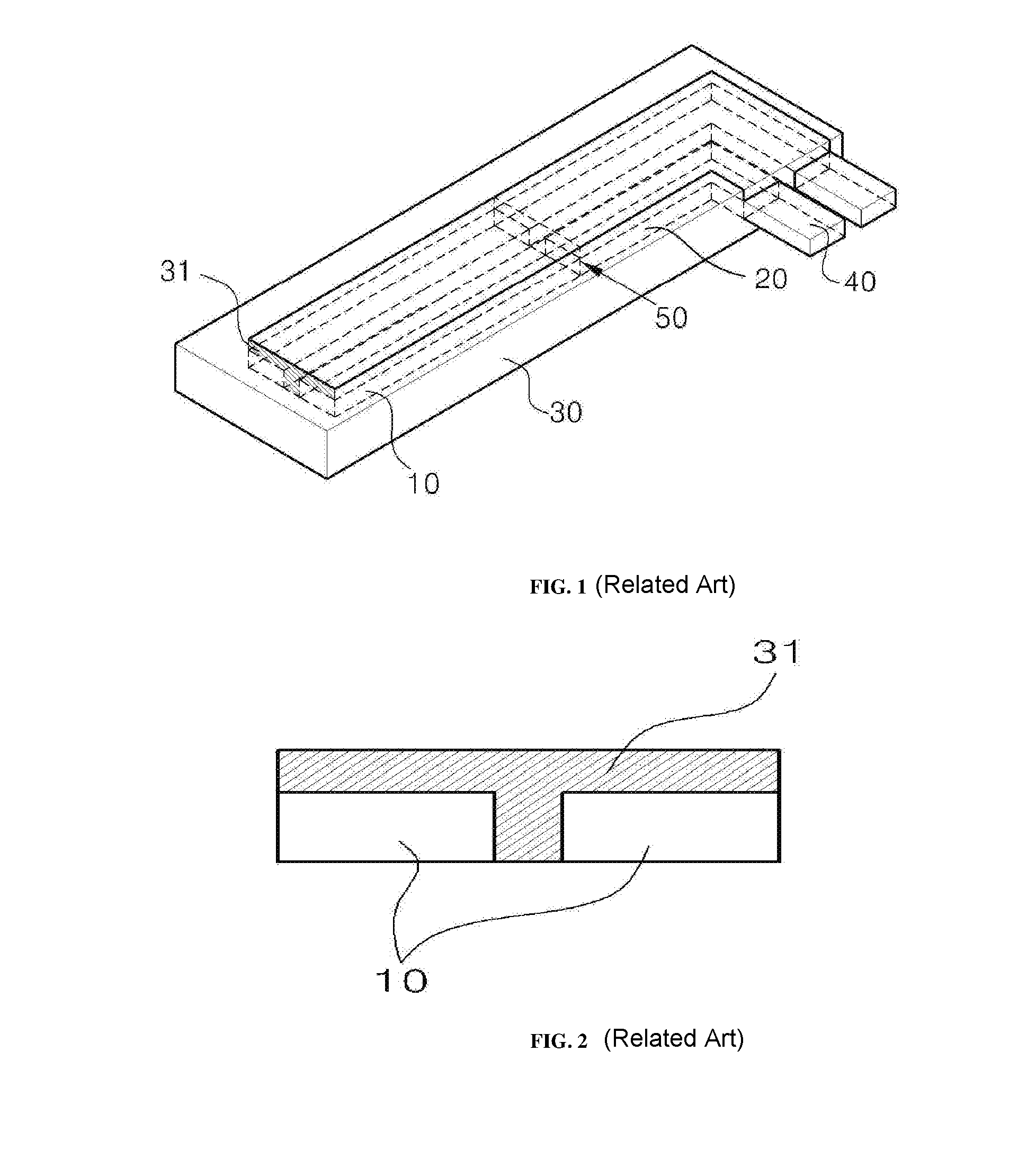
CROSS REFERENCE TO RELATED APPLICATION[0001]The present application claims the benefit of Korean Patent Application No. 10-2014-0183571 filed in the Korean Intellectual Property Office on Dec. 18, 2014, the entire contents of which are incorporated herein by reference.BACKGROUND[0002]1. Technical Field[0003]The present disclosure relates to a stator slot temperature sensor assembly and a method of manufacturing the same and, more particularly, to a stator slot temperature sensor assembly including a flexible substrate and a laminate slot and a method of manufacturing the same.[0004]2. Description of the Related Art[0005]In general, the slot of the stator core of a power generator includes a temperature sensor for continuously monitoring the state in order to prevent overheating or a undesirable state.[0006]FIG. 1 is a perspective view of a conventional stator slot temperature sensor assembly, and FIG. 2 is a cross-sectional view of the conventional stator slot temperature sensor ass...

Claims


Application Information

Patent Timeline
IPC IPC(8): G01K7/18
CPCG01K7/18G01K7/16H05K1/185H05K3/0011H05K2201/10757G01K1/08G01K1/14H02K11/00
Inventor KIM, YOUNG WOOKLEE, SUNG JAEJEONG, DONG UK
Owner DOOSAN HEAVY IND & CONSTR CO LTD
Learn More