Output member

a technology of output member and output plate, which is applied in the field of output member, can solve the problems of high strain rate testing cost and complexity, damage to the transmission bar itself or the associated strain gauge, and increase the cost and complexity of such high strain rate testing, and achieve the effect of high strain rate loading of test specimens

Inactive Publication Date: 2016-06-23
ROLLS ROYCE PLC
View PDF6 Cites 23 Cited by
  • Summary
  • Abstract
  • Description
  • Claims
  • Application Information

AI Technical Summary

Benefits of technology

[0015]The output member of the disclosure allows high strain rate loading of a test specimen or structure at a near constant strain rate until the applied load reaches a critical level. At this point the cap portion fails in plastic shear, with the circular stub shearing away from the body of the cap portion.
[0016]The disc-shaped cap portion therefore functions as a mechanical fuse to protect the transmission bar and its associated strain gauges from damage resulting from excessively high impact loads.

Problems solved by technology

A known problem with the Hopkinson pressure bar apparatus is that at impacting velocities above 20 m / s, the stresses generated in the incident and transmission bars may damage the bars themselves or the associated strain gauges.
This increases the cost and complexity of such high strain rate testing.
Furthermore, once the test specimen is fully compacted, the impact loading may damage the transmission bar.

Method used


Image

  • Output member
  • Output member

Examples


Embodiment Construction

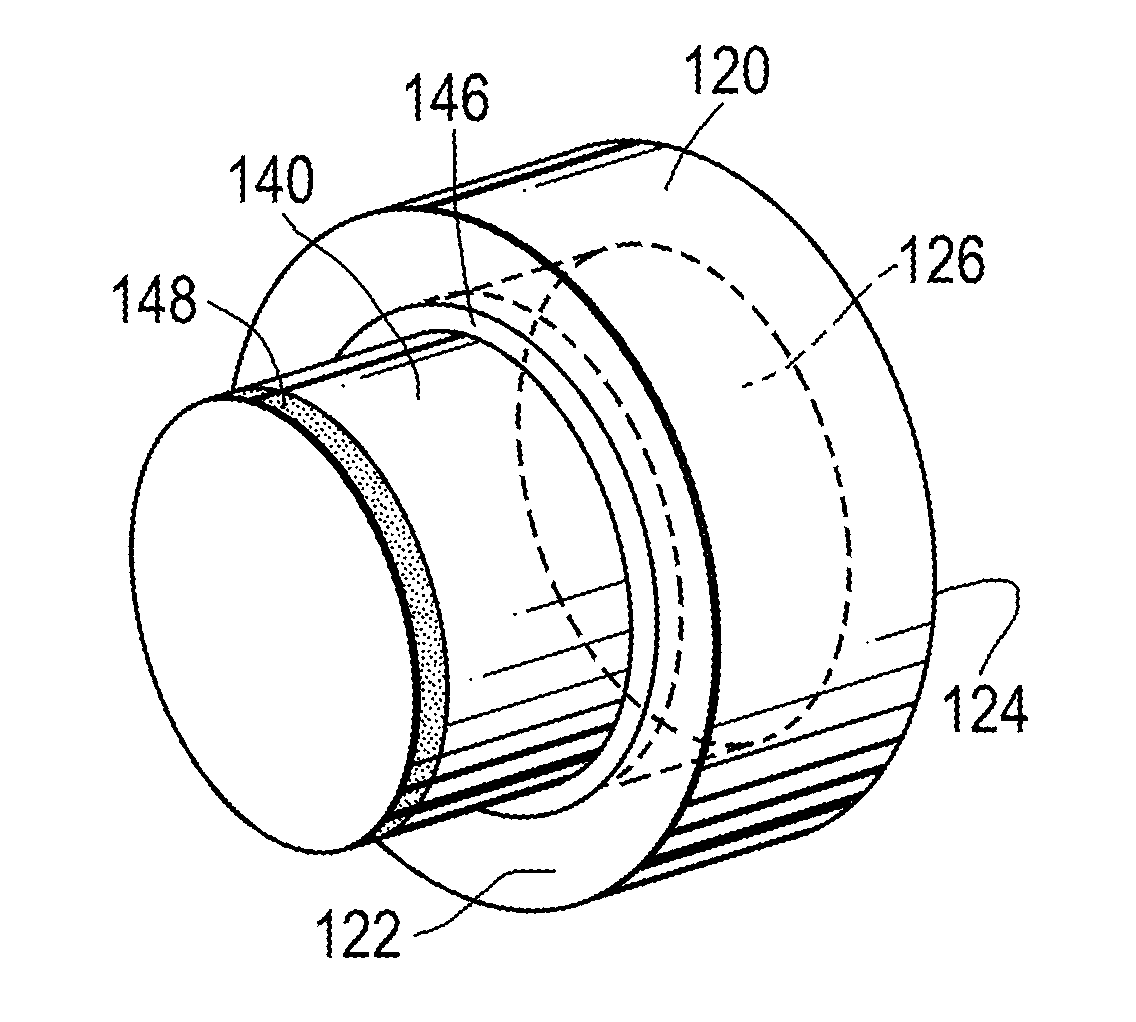
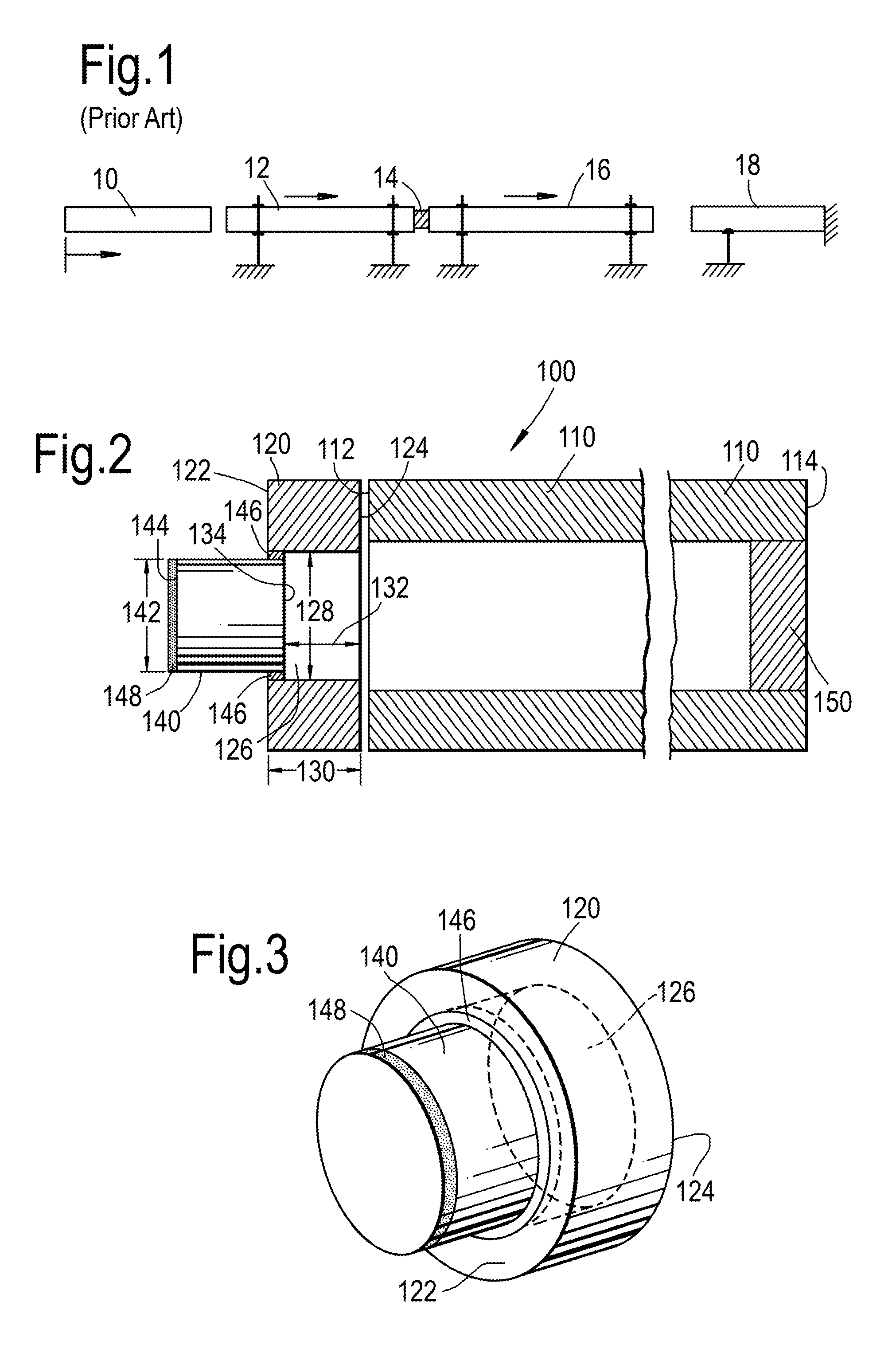
[0042]Referring to FIGS. 2 and 3, an output member for a Direct Impact Hopkinson pressure bar according to a first embodiment of the disclosure is designated generally by the reference numeral 100.

[0043]The output member 100 comprises an elongate tube portion 110 and a disc-shaped cap portion 120. The tube portion 110 has a first end 112 and an opposite second end 114.

[0044]The cap portion 120 has a first face 122, an opposite second face 124, and an axial length 130. The axial length 130 extends between the first face 122 and the second face 124.

[0045]A circular stub 140 protrudes from a centre of the first face 122 of the cap portion 120.

[0046]A circular cavity is formed in the second face 124 of the cap portion 120. Each of the circular stub 140 and the circular cavity 126 is concentric with the cap portion 120.

[0047]A diameter 128 of the circular cavity 126 is greater than a diameter 142 of the circular stub 140. In the present arrangement, the diameter 142 of the circular stub ...


PUM

PropertyMeasurementUnit
axial lengthaaaaaaaaaa
velocitiesaaaaaaaaaa

Abstract

An output member for a Direct Impact Hopkinson pressure bar includes an elongate tube portion and a disc-shaped cap portion. The tube portion has a first end and an opposite second end, while the cap portion includes a first face and an opposite second face. A circular stub protrudes from a centre of the first face, and a circular cavity is formed in the second face. Each of the stub and the cavity is concentric with the cap portion, with a diameter of the cavity being greater than a diameter of the stub. The second face of the cap portion is positioned in intimate contact with the first end of the tube portion, with the cap portion being concentric with the tube portion.

Description

[0001]This disclosure claims the benefit of UK Patent Application No. GB1422940.5, filed on 22 Dec. 2014, which is hereby incorporated herein in its entirety.FIELD OF THE DISCLOSURE[0002]The present disclosure relates to an output member for a Direct Impact Hopkinson pressure bar.BACKGROUND TO THE DISCLOSURE[0003]A Split Hopkinson pressure bar is a mechanical test instrument that is used to characterise the dynamic response of materials when subjected to high strain rates.[0004]FIG. 1 shows a schematic arrangement of a conventional Split Hopkinson pressure bar. A striker bar 10 is projected towards, and impacts against, a first end of the incident bar 12. Typical impact velocities range from 10 m / s to 20 m / s. This impact creates a stress wave that propagates along the incident bar towards the test specimen 14 that is positioned between the opposite second end of the incident bar 12 and a first end of the transmission bar 16.[0005]When the stress wave reaches the test specimen 14 it ...

Claims


Application Information

Patent Timeline
Patent Type & Authority Applications(United States)
IPC IPC(8): G01N3/30
CPCG01N3/30G01L5/0052G01N3/307G01N2203/0055G01N2203/0098G01N2203/0441G01N3/02
Inventor MACDOUGALL, DUNCAN ALEXANDER STUARTBROWN, KEVIN ANTHONYJACKSON, MATTHEW DAVIDWHITE, ROGER
Owner ROLLS ROYCE PLC
Why Eureka
Try Eureka