
Wear-proof tester for retainer in needle cage

a technology of wear-proof tester and retainer, which is applied in the direction of measurement devices, instruments, scientific instruments, etc., can solve the problems of large-scale alternation of the tester, adversely required to make the testing device large-scale, and the test cannot be carried out according to the required engine conditions, etc., to achieve compact construction, easy to make, and simple construction

Active Publication Date: 2016-06-23
NIPPON THOMPSON
View PDF10 Cites 10 Cited by
  • Summary
  • Abstract
  • Description
  • Claims
  • Application Information

AI Technical Summary

Benefits of technology

The wear-proof tester described in the patent is a device that can reproduce the condition in which a retainer gets flexed in an actual engine. It allows for controlled testing of the retainer under various pressure and speed conditions. This tester is compact, easy to control, and can be used to evaluate the performance of the retainer in the engine.

Problems solved by technology

As a result, the surface treatment skin has torn off and thereafter the wear-proof test couldn't be executed according to the required engine conditions.
H04-24 531, it is adversely required to make the testing device large scaled to resist large centrifugal load.
Large-scale alternation of the tester was very tough because requiring large-scale design alternation and risking high cost.
Thus, as the result higher contact surface-pressure than in the actual engine affected against the outside surface of the retainer, the surface-treatment skin was torn off from the outside circular surface of the retainer and therefore the wear-proof test could not be made on the assumption of actual conditions of the engine.

Method used


Image

  • Wear-proof tester for retainer in needle cage
  • Wear-proof tester for retainer in needle cage
  • Wear-proof tester for retainer in needle cage

Examples


Embodiment Construction

[0038]The wear-proof tester of the present invention is preferably used for evaluation of wear-proof performance of surface treatment done on a retainer in the needle cage which is incorporated in, for example, a big end of the connecting rod used in the four-cycle engine.

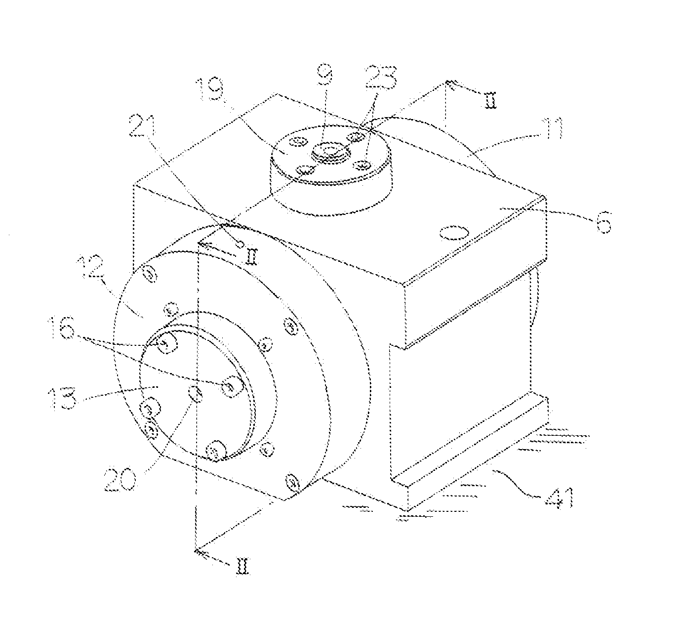
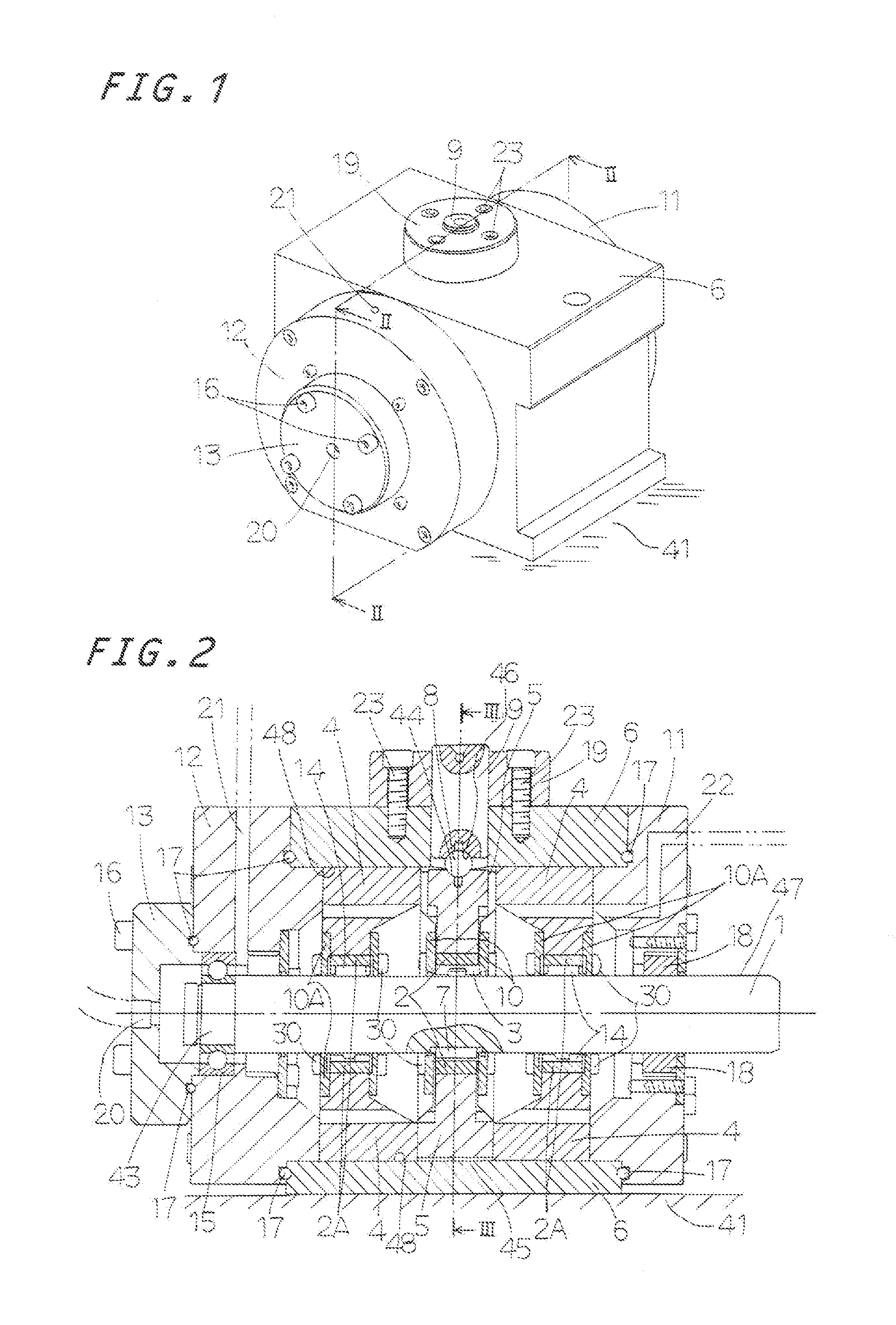
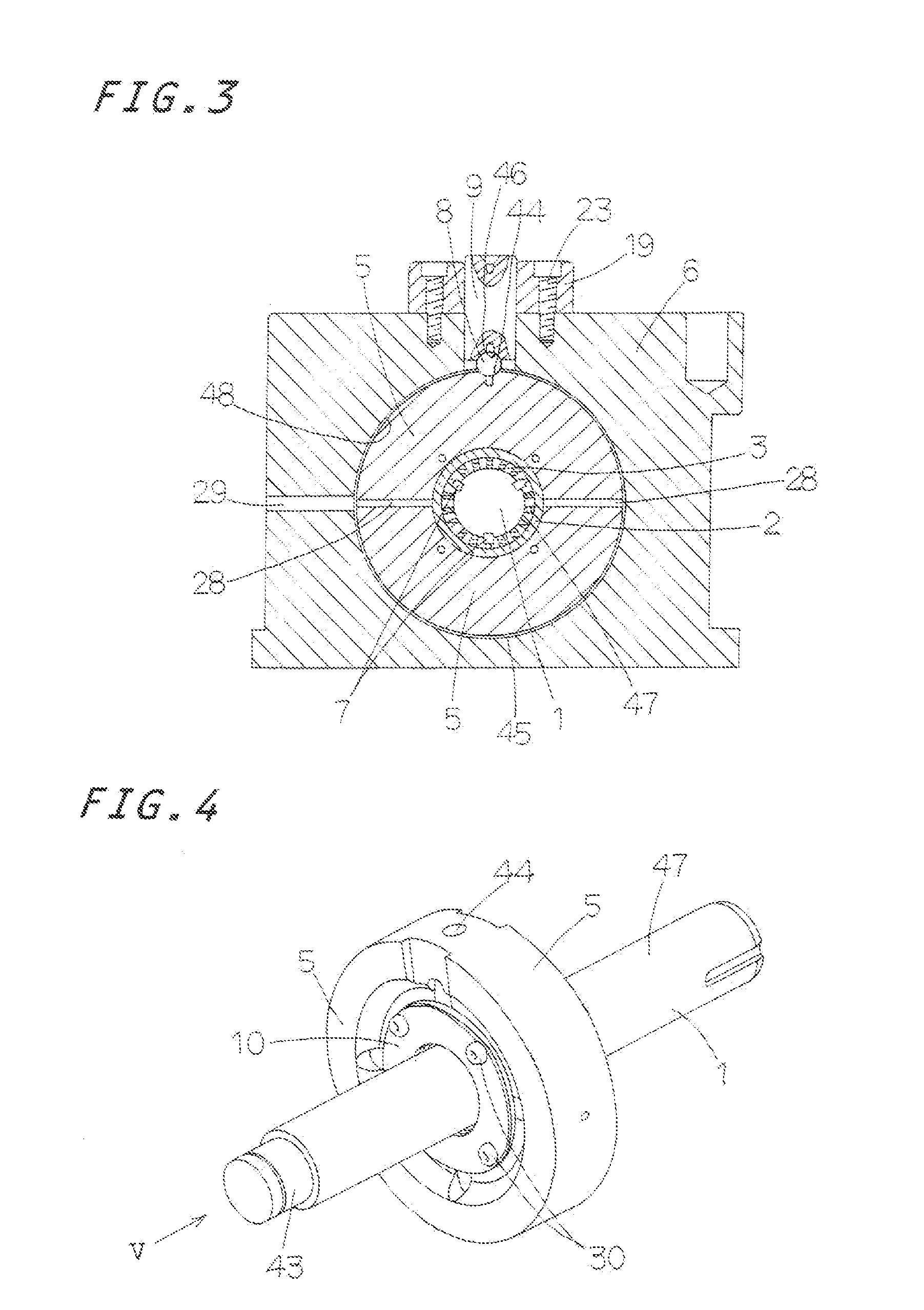
[0039]A wear-proof tester in a needle cage of the present invention will be explained in detail with reference to the accompanying drawings. The wear-proof tester in a needle cage is suited, for example, to the wear-proof tester for needle cage for the surface-treated retainer for the four-cycle engines. A motor, not shown, serving as an energizing means is underneath a basement 41 on which is installed a casing 6 of the wear-proof tester. The wear-proof tester in a needle cage is constituted to bear a radial load F2 (refer to FIG. 11). The needle cage is constituted with a retainer 3 having an outside circular surface 34 subjected to surface treatment and made with more than one windows or pockets spaced circularl...


PUM

PropertyMeasurementUnit
surface pressureaaaaaaaaaa
flexing forceaaaaaaaaaa
centrifugal forceaaaaaaaaaa

Abstract

A wear-proof tester to evaluate an anti-frictional performance of surface treatment carried on a needle cage. The needle cage is subjected to flex under the centrifugal force of composite revolution and rotation. Wear-proof test of surface treatment is carried by sliding contact between the outside circular surface of the retainer and the inside circular surface of the outside wheel. The retainer with no roller is fastened on a rotary shaft with leaving a clearance between them. A radial load is applied to retainer through a test outside wheel to get the retainer flexed to make sliding contact over a predetermined area between the outside circular surface of the retainer and the inside circular surface of the outside wheel. This wear-proof tester is applicable to the wear-proof tests of various materials other than the wear-proof test of the retainer made of various materials.

Description

FIELD OF THE INVENTION[0001]The present invention relates to a wear-proof tester to evaluate an anti-frictional performance of surface treatment carried on a needle cage which is, for example, incorporated in a big end of a connecting rod used in a four-stroke-cycle engine.BACKGROUND OF THE INVENTION[0002]The needle cage used in engines generally is incorporated in a big end of a connecting rod and mainly composed of more than one needle roller and a retainer to keep in place the needle rollers. With the needle cage incorporated in the connecting rod, the retainer keeping the rollers therein would be subjected to flexing force under a large centrifugal force exerted during revolution of a crank shaft.[0003]The retainer while subjected to centrifugal force makes revolution to make sliding contact with an inside circumference of the big end of the connecting rod. To cope with this, the outside circular surface of the retainer generally is applied with any plated layer such as cupper-p...

Claims


Application Information

Patent Timeline
Patent Type & Authority Applications(United States)
IPC IPC(8): G01N19/02
CPCG01N19/02G01N3/56
Inventor NAGAO, SHOJIYANAGITANI, AKIHIDE
Owner NIPPON THOMPSON
Learn More