
Method for fabricating vacuum fixturing using granular media

a technology of granular media and vacuum fixture, which is applied in the direction of manufacturing tools, work holders, coatings, etc., can solve the problems of high speed process for machining thin walled parts, difficult to shape into intricate parts, and parts that wander on the machining fixtur

Active Publication Date: 2016-06-30
TECHNICAL TOOLING L L C +1
View PDF8 Cites 10 Cited by
  • Summary
  • Abstract
  • Description
  • Claims
  • Application Information

AI Technical Summary

Benefits of technology

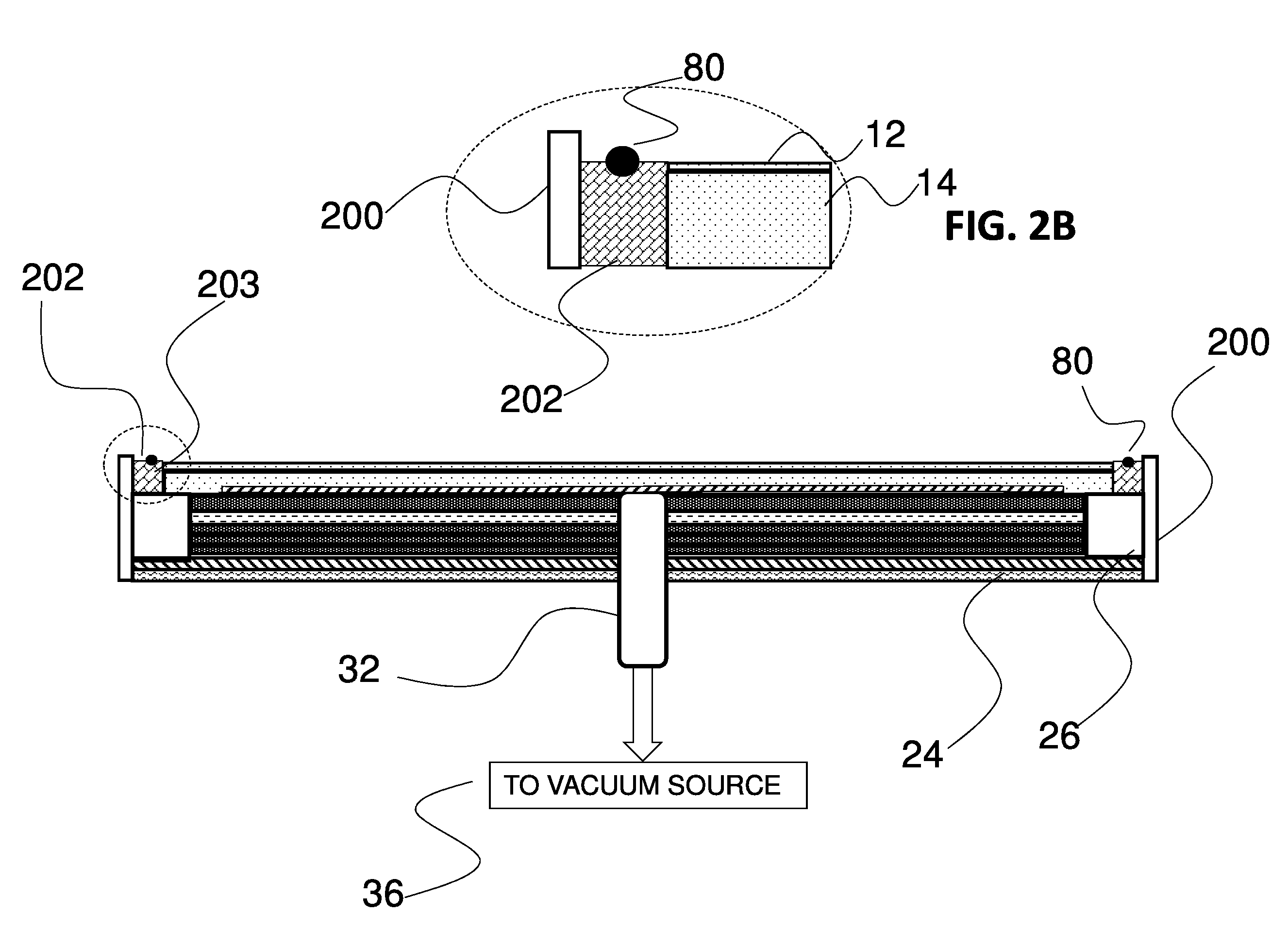
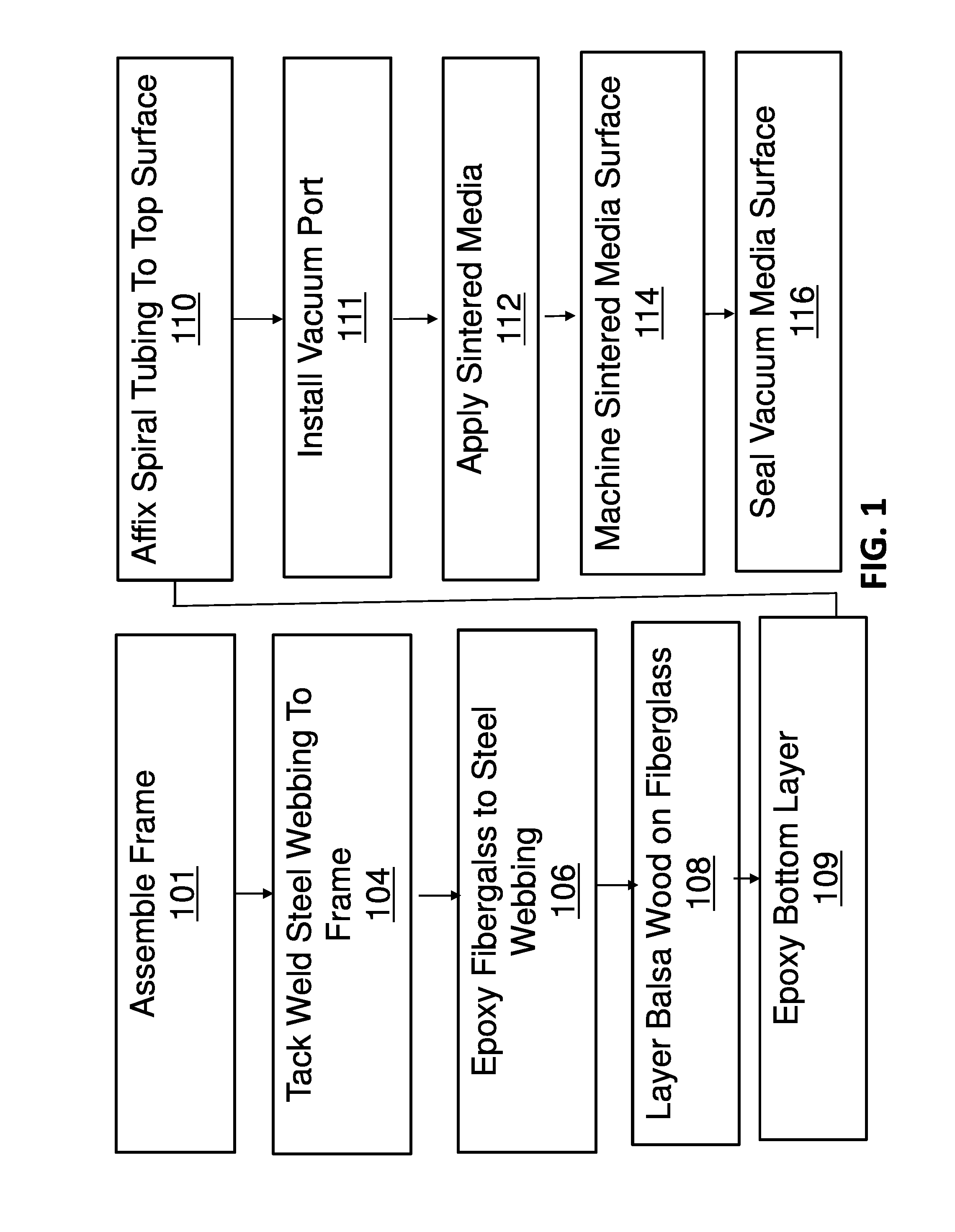
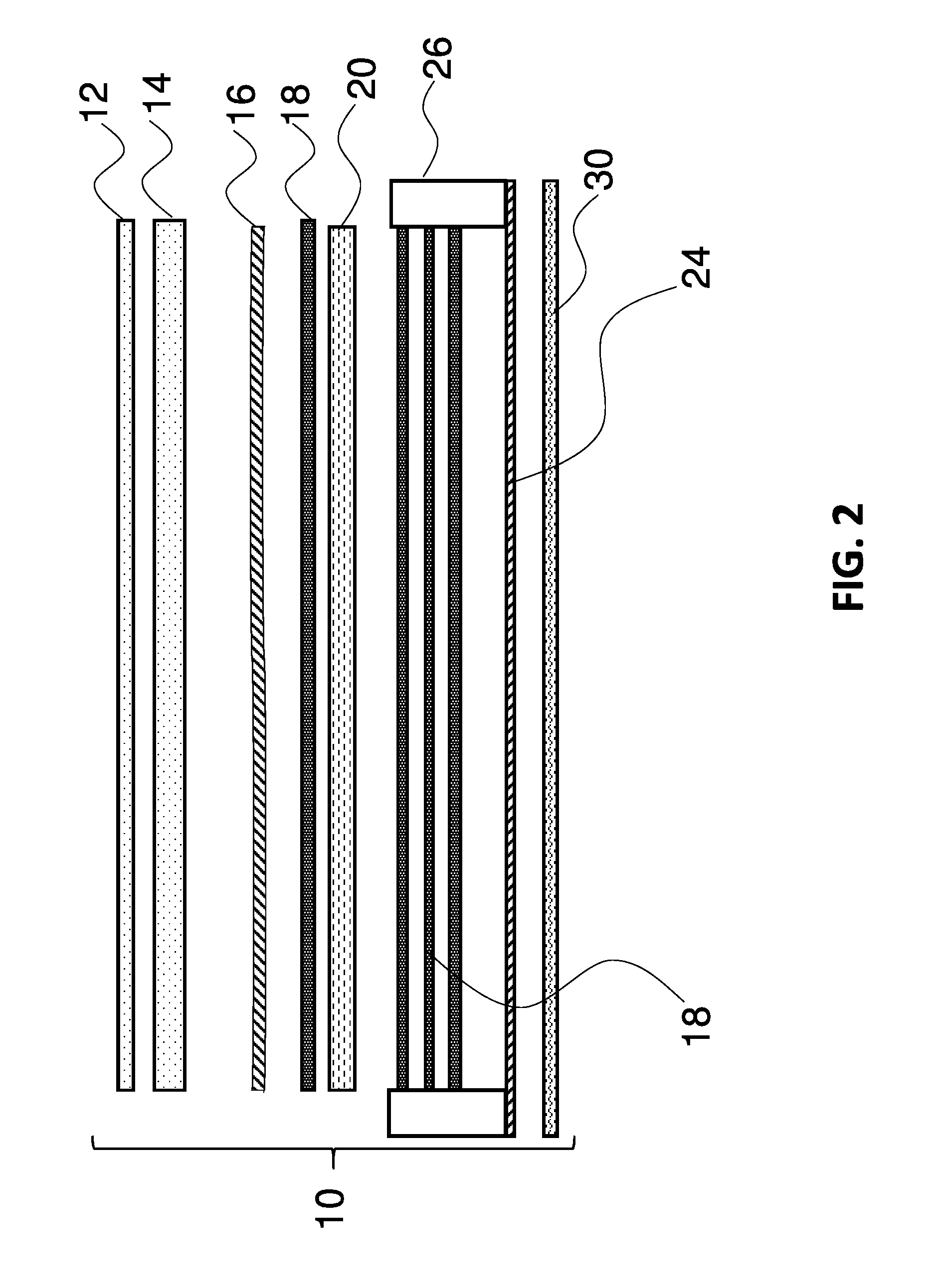
The patent describes a method for making a vacuum table using porous granular media. The process involves affixing a sheet of steel webbing to a frame, adding layers of fiberglass, installing a vacuum port, and layering a mixture of granular media made of sintered iron grit or epoxy resin over the fiberglass layers. The granular media can be encompassed by a spiralwrap tubing or added in a serpentine pattern. An additional stiffener made of fiberglass and balsa wood can be added between the fiberglass layers. The process also involves applying a fiberglass lining to the inside of a tooling fixture, creating a vacuum in the part being formed, and using the tooling fixture to conform the part to its final shape. The technical effect of this method is an improved vacuum forming process for thermally pliable parts.

Problems solved by technology

As a result, manufacturers are faced with machining thin walled parts using high speed processes.
Such parts are prone to wander on a machining fixture when being drilled or milled, for example.
Unfortunately, these materials are relatively costly and hard to shape into intricate parts.
Because epoxy resin is typically used to bind round micro-balloons comprising such older materials it cannot easily be shaped or repaired if damaged.
A significant drawback is that, since such materials have inherently smooth surfaces, they do not prevent slippage of many thin-walled parts while the parts are undergoing machining.

Method used


Image

  • Method for fabricating vacuum fixturing using granular media
  • Method for fabricating vacuum fixturing using granular media
  • Method for fabricating vacuum fixturing using granular media

Examples


Embodiment Construction

[0041]The examples presented herein are for the purpose of furthering an understanding of the invention. The examples are illustrative and the invention is not limited to the example embodiments.

[0042]Unless the context requires otherwise, throughout the specification and claims which follow, the word “comprise” and variations thereof, such as, “comprises” and “comprising” are to be construed in an open, inclusive sense that is as “including, but not limited to.”

[0043]Reference throughout this specification to “one example” or “an example embodiment,”“one embodiment,”“an embodiment” or combinations and / or variations of these terms means that a particular feature, structure or characteristic described in connection with the embodiment is included in at least one embodiment of the present disclosure. Thus, the appearances of the phrases “in one embodiment” or “in an embodiment” in various places throughout this specification are not necessarily all referring to the same embodiment. Fu...


PUM

PropertyMeasurementUnit
thicknessaaaaaaaaaa
thicknessaaaaaaaaaa
vacuumaaaaaaaaaa

Abstract

A method for fabricating vacuum tooling is disclosed using porous granular media. A sheet of steel webbing is affixed to a frame. A plurality of layers of fiberglass is affixed to the webbing. A vacuum port is installed through the webbing and plurality of layers of fiberglass. A granular media is mixed with epoxy to form a granular mixture. The granular mixture is layered over the plurality of layers of fiberglass to form a flat surface and machined for uniformity before sealing.

Description

CROSS-REFERENCE TO RELATED APPLICATIONS[0001]This application claims priority from and is a non-provisional application of co-pending U.S. provisional application No. 62 / 063,816, filed Oct. 14, 2014, entitled “METHOD FOR FABRICATING VACUUM FIXTURING USING SINTERED MEDIA.” U.S. application No. 62 / 063,816 is hereby incorporated by reference.FIELD OF THE INVENTION[0002]The present invention relates to methods for holding thin metal and / or composite surfaces for machining, and, more particularly, to a method for making a vacuum tooling fixture from a porous granular material.BACKGROUND OF THE INVENTION[0003]Current manufacturing demands faced by the aerospace industry require thinner, stronger parts in order to meet constantly more demanding standards for lowering costs, improving safety and increasing fuel mileage. As a result, manufacturers are faced with machining thin walled parts using high speed processes. Machining complex shapes with walls having thickness in the range of, for e...

Claims


Application Information

Patent Timeline
Patent Type & Authority Applications(United States)
IPC IPC(8): B23Q3/08B23Q3/06B05D3/00
CPCB23Q3/088B05D3/00B05D2503/00B05D2601/20B05D2504/00B23Q3/065B29K2263/00B29C70/44B29K2063/00
Inventor READ, ROBERT W.OLBERG, JEFFERY H.
Owner TECHNICAL TOOLING L L C
Learn More