Aircraft rear structure

a rear structure and aircraft technology, applied in the field of rear structures, can solve the problems of not optimizing the structure for support, the reinforcement elements constitute a significant weight on the curved rear pressure bulkhead, etc., and achieve the effect of increasing the passenger capacity of the cabin

Active Publication Date: 2016-06-30
AIRBUS OPERATIONS SL
View PDF0 Cites 7 Cited by
  • Summary
  • Abstract
  • Description
  • Claims
  • Application Information

AI Technical Summary

Benefits of technology

[0021]Cabin passenger capacity could be increased if the rear pressure bulkhead is moved backwards to the position of the lifting surface.

Problems solved by technology

This bulkhead configuration requires additional stiffeners and other reinforcements to support the skin and load in case of reverse pressure cases, when there is negative pressure difference in the cabin for which the concave shape is not effective.
These reinforcement elements constitute a significant penalty weight on the curved rear pressure bulkhead.
On flat RPB solutions, the structure is not optimized to sustain positive cabin pressure loads as it is not able to work as a membrane, but this solution already includes stiffeners and reinforcement elements that are effective for both positive and negative pressure load cases.

Method used


Image

  • Aircraft rear structure
  • Aircraft rear structure
  • Aircraft rear structure

Examples


first embodiment

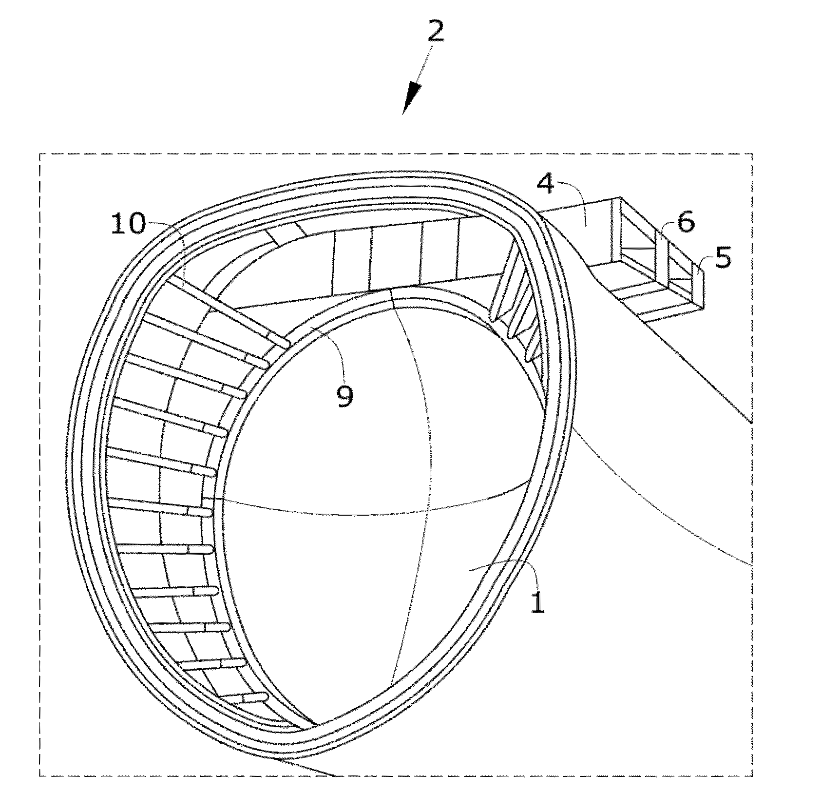
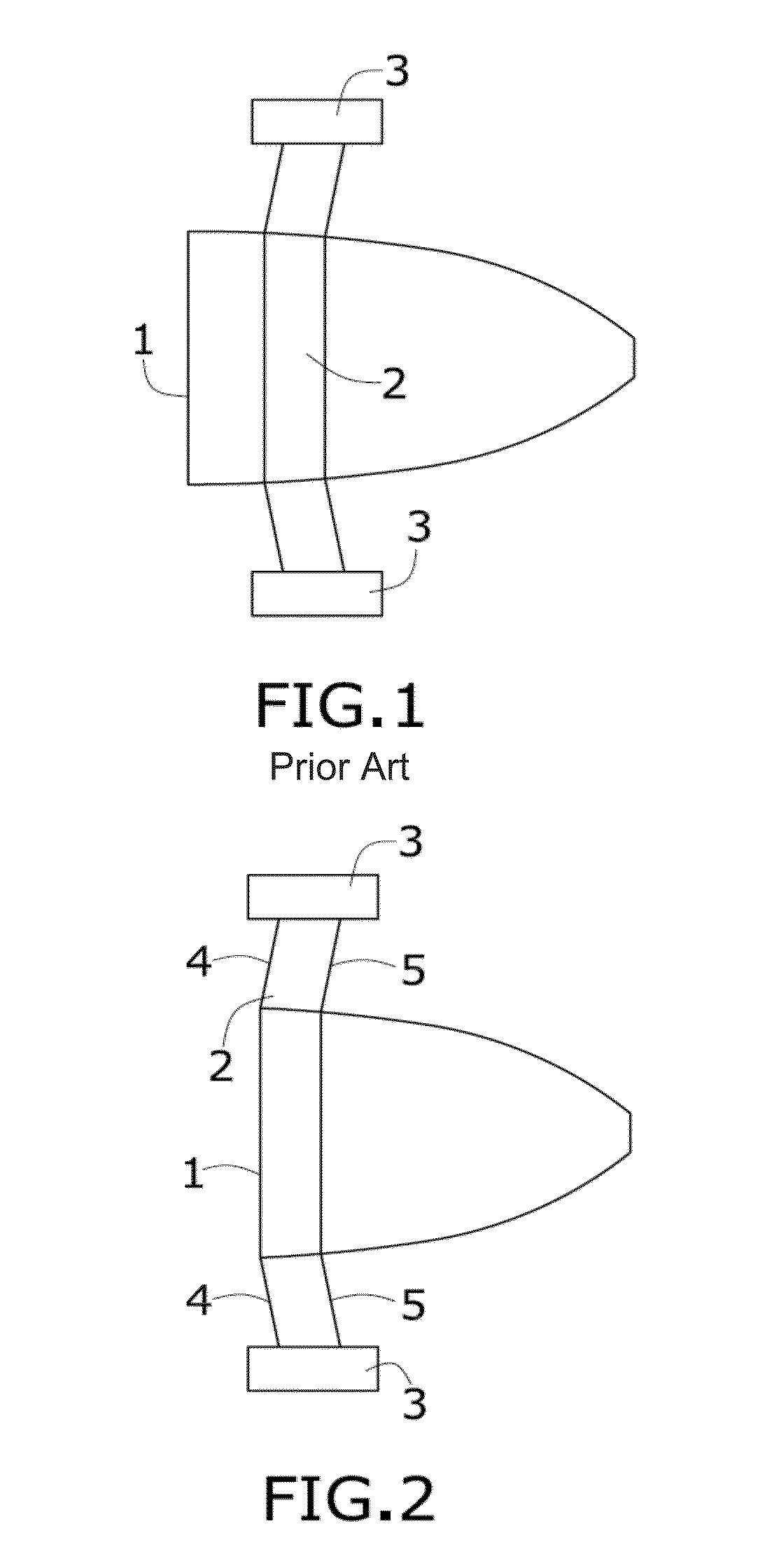
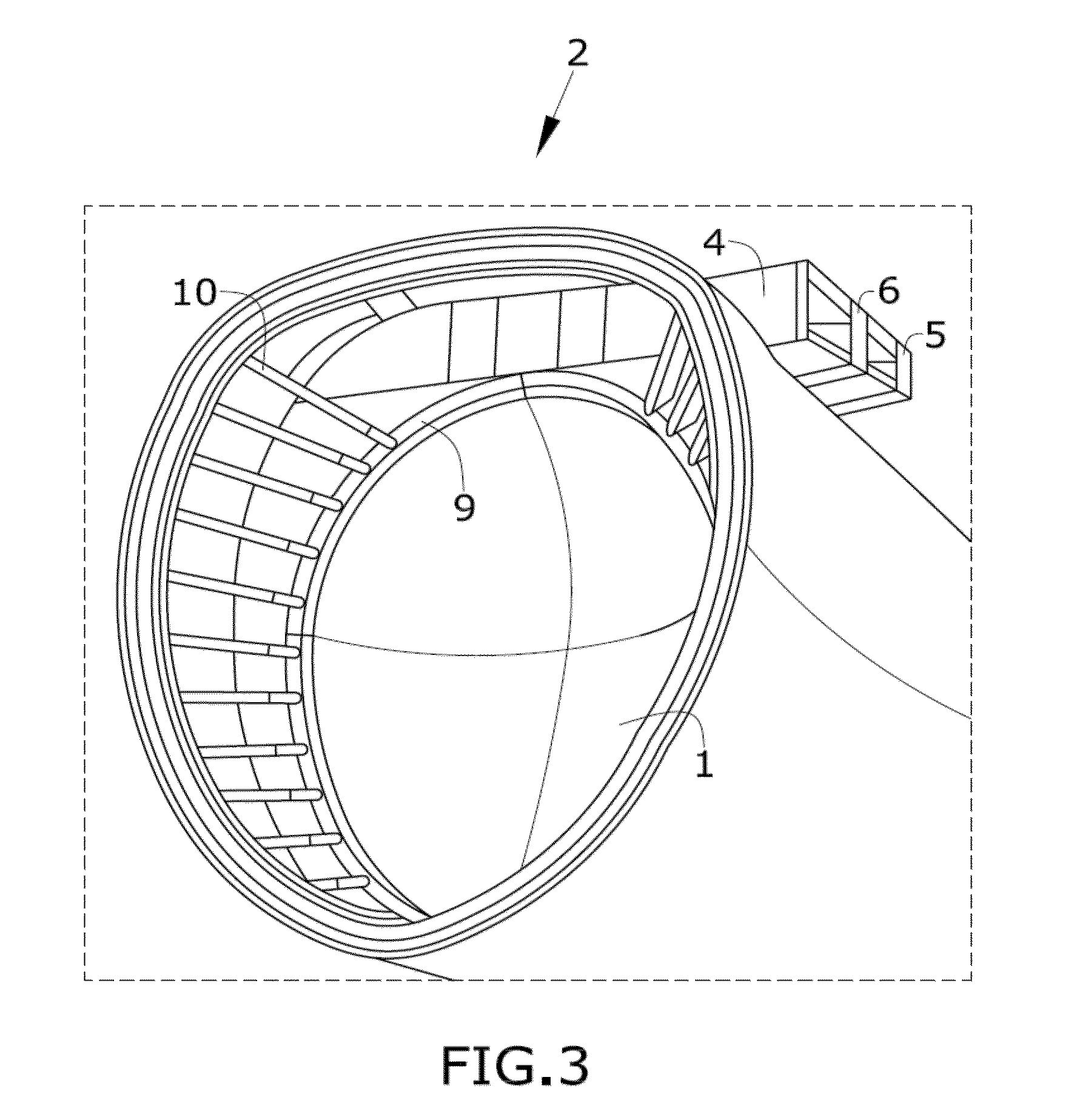
[0036]FIGS. 2 and 3 show the invention, showing a rear pressure bulkhead (1) integrated with the pylon (2). More specifically, the frame (9) of the bulkhead (1) is aligned with the front spar (4) of the pylon (2). FIG. 3 shows a curved bulkhead (1) aligned with the front spar (4). The bulkhead (1) could also be aligned with the rear (5) or an intermediate (6) spar. This solution could require additional intercostals (10) extending between the frame (9) and the fuselage to transmit the membrane loads from the bulkhead (1) to the fuselage.

[0037]The alignment could be achieved by integrating all the components, i.e., the bulkhead (1) and the lifting surface spar in one element or, to the contrary, by joining these components together. It has to be understood for this application that a structure is called integrated when all its structural components are manufactured in one shot. Moreover load transfer is improved due to the continuous integrated structure.

[0038]FIG. 4 shows another em...

third embodiment

[0041]FIG. 5 shows the invention wherein the rear pressure bulkhead (1) is a sandwich flat bulkhead (1) which is also aligned with the front spar (4). In this case the integration of the floor (8) is different as the floor beam (7) is more difficult to join to the sandwich panel of the rear pressure bulkhead (1). In this embodiment, it is preferred to separate the floor beam (7) from the bulkhead (1). The floor (8) is being sustained by a cantilever structure (12) independent of the bulkhead (1) and not supported on it.

[0042]Although the embodiments show pylons (2) that are located at an upper position with respect to a section of the fuselage, pylons (2) located at a lower position are also possible.


PUM


Abstract

An aircraft rear structure that comprises a rear pressure bulkhead, and a lifting surface located at both sides of the fuselage of the aircraft. The lifting surface comprises spars extending in the longitudinal direction of the lifting surface. The pressure bulkhead is aligned with one of the spars of the lifting surface.

Description

CROSS-REFERENCES TO RELATED APPLICATIONS[0001]This application claims the benefit of the European patent application No. 14382588.3 filed on Dec. 30, 2014, the entire disclosures of which are incorporated herein by way of reference.FIELD OF THE INVENTION[0002]The present invention refers to a rear structure comprising a pressure bulkhead of an aircraft. The rear structure is also related to the lifting surfaces located at both sides of the fuselage. For the purpose of simplifying the following description, the term “lifting surface” will be used to describe not only wings, but also stabilizing and / or supporting surfaces, such as horizontal stabilizers or pylons for supporting the engines of the aircraft.BACKGROUND OF THE INVENTION[0003]A tail structure which adjoins a fuselage section of an aircraft includes a fuselage, lifting surfaces located at both sides of the fuselage such as wings or pylons for supporting the engines of the aircraft or other supporting structures, and a bulkh...

Claims


Application Information

Patent Timeline
Patent Type & Authority Applications(United States)
IPC IPC(8): B64C1/10B64C5/00
CPCB64C5/00B64C1/10B64C1/068B64D29/04B64C1/16B64C1/26B64C3/185B64C5/02
Inventor MARTINO GONZALEZ, ESTEBANFOLCH CORTES, DIEGOGOYA ABAURREA, PABLOLINARES MENDOZA, SANDRA
Owner AIRBUS OPERATIONS SL
Why Eureka
Try Eureka