Compression indentation fastener device

a fastener and compression indentation technology, applied in the direction of screws, fastening means, nails, etc., can solve the problems of failure of fasteners, failure of nail heads or shanks, extensive damage to buildings, etc., to eliminate failure mode, improve retention capability, and superior pull-through resistance

Inactive Publication Date: 2016-06-30
SR SYST
View PDF0 Cites 6 Cited by
  • Summary
  • Abstract
  • Description
  • Claims
  • Application Information

AI Technical Summary

Benefits of technology

[0021]Accordingly, the fastener devices described herein and the method for its manufacture provide a number of advantages and overcome the short comings of existing fasteners and associated methods for their production. The fastener head design described herein provides substantially improved retention capabilities combined with superior pull-through resistance compared to small-head fasteners and existing enlarged head fasteners. Both convergent transition portion and the at least one ridge formation reinforce the head of the subject enlarged head fastener device in order to substantially eliminate the failure mode that occurs in other fasteners where the enlarged head is turned inside out like an umbrella after pulling through the substrate material. Because the head of the subject enlarged head fastener device is much less prone to deformation, the pull-through resistance of the disclosed enlarged head fastener device is higher. In addition, the pull-through resistance of the disclosed enlarged head fastener device increases to a greater extent when the thickness of the substrate material is increased. Testing has shown that this level of fastener performance is not achieved by the small-head fasteners or the other enlarged head fasteners described above. Advantageously, the teachings set forth herein can be applied to a wide range of different fastener types, including nail-like fasteners, screw-like fasteners, and bolt-like fasteners.

Problems solved by technology

When a typical fastener is installed in a typical wood and / or wood-like substrate material, a tug-a-war of sorts results between the substrate material and the fastener.
The weakest link in the pull-through withdrawal tug-of-war will fail first such that one of three failure modes results.
A third failure mode, less common than the first and second failure modes, is fastener failure, where the nail head or the shank fails due to breakage, bending, or shearing.
When any one of these three failure modes occur, the wood roof decking substrate material comes off resulting in the building suffering extensive damage and property loss.
Shank features such as barbs, ring shanks, spirals, and flutes have been shown to lose significant withdrawal resistance when the substrate material is subjected to environmental conditions, which causes the dry shrinking of wood substrate fibers over long periods of time.
In addition, shank features such as barbs, ring shanks, spirals, and flutes have been shown to lose significant withdrawal resistance when the nail and substrate material are subjected to vibration, which may be created by storm winds beating upon a structure, seismic activity generated by tornadoes beating the ground as they travel, and seismic activity associated with earth quakes and ground shifting.
One short coming of the fasteners described in these patents is that the heads can easily cut and / or rupture the surface fibers of the wood and / or wood-like substrate material.
While using a washer-type device does increase the bearing surface, it also increases the relative thickness of the head of the fastener causing it to protrude above the surface of the substrate material.
If the fastener and washer combination is driven in to be flush with the surface of the substrate material, then the substrate material can often be cut, compromised, and / or damaged such that it is easily susceptible to further deformation and subsequent loss of structural integrity.
A short coming of the fasteners disclosed in these patents includes that the washer-like devices are not designed to prevent cutting and / or rupturing the surface fibers of the wood and / or wood-like material substrate.
The benefit of the enlarged head size compared to the shank of the fastener is limited because of the inherent detrimental benefits of the geometric shape of the head design.
Specifically, enlarged head nails have been shown to include several significant failure modes.
One failure mode occurs where the surface fibers of the wood substrate material become ruptured and split from the initial setting of the nail before pull-through forces are applied due to the sharp edges on the underside of the head.
Another failure mode occurs where the enlarged heads of the nails become noticeably distorted and wobbled after pulling through the substrate material, resembling an umbrella turned inside out as a result of strong winds.
In other words, in spite of the enlarged head, independent third party testing reveals that as the thickness of the substrate material increases, there is not a corresponding increase in the pull-through resistance for nails of this design.
Another disadvantage associated with such enlarged head fasteners lies with the manufacturing process for such fasteners.
In other words, the diameter of the head after a first hammer strike is insufficient and one or more additional hammer strikes are required to continue to push the material of the wire outward to form the enlarged head.
This increases manufacturing costs by slowing down the yield of the manufacturing process.

Method used


Image

  • Compression indentation fastener device
  • Compression indentation fastener device
  • Compression indentation fastener device

Examples


Embodiment Construction

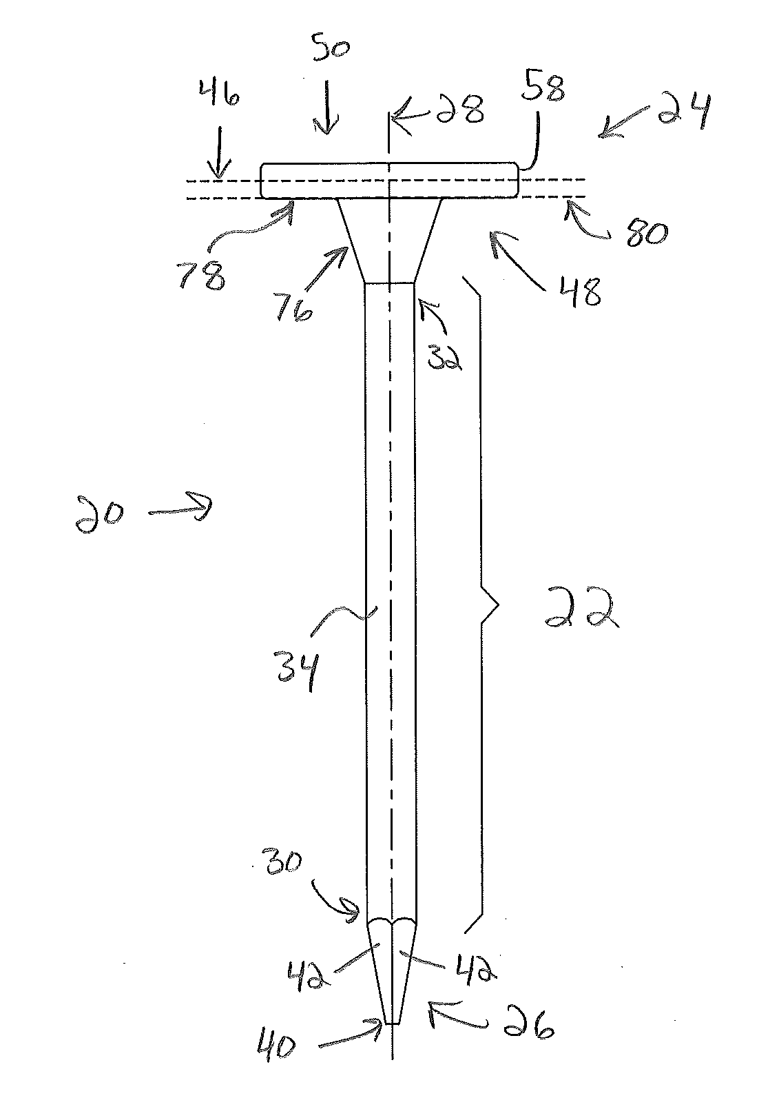
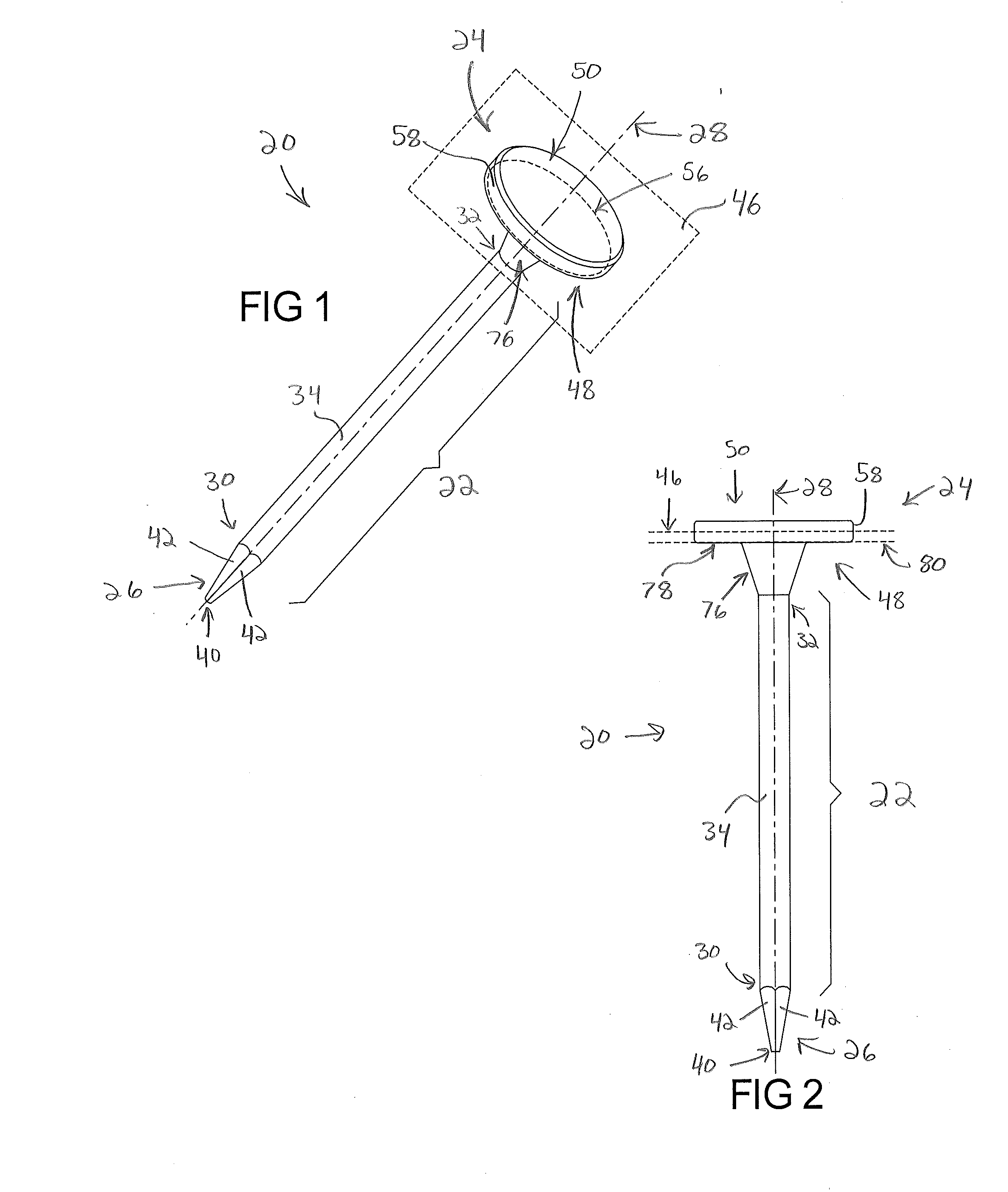
[0053]Referring to the Figures, wherein like numerals indicate corresponding parts throughout the several views, an enlarged head fastener device 20 is illustrated.

[0054]Example embodiments will now be described more fully with reference to the accompanying drawings. Example embodiments are provided so that this disclosure will be thorough, and will fully convey the scope to those who are skilled in the art. Numerous specific details are set forth such as examples of specific components, devices, and methods, to provide a thorough understanding of embodiments of the present disclosure. It will be apparent to those skilled in the art that specific details need not be employed, that example embodiments may be embodied in many different forms and that neither should be construed to limit the scope of the disclosure. In some example embodiments, well-known processes, well-known device structures, and well-known technologies are not described in detail.

[0055]The terminology used herein i...


PUM


Abstract

An enlarged head fastener device and method for manufacturing the same is described. The enlarged head fastener device includes a shank and a head. The head extends outwardly from the shank in a transverse plane to define a head periphery. The head has an anterior side and a posterior side. The anterior side includes a bearing surface and a convergent transition portion that reinforces the head. The convergent transition portion extends between a large end adjacent the bearing surface to a small end adjacent the shank. At least one ridge formation projects from the anterior side of the head providing additional reinforcement. The ridge formation extends continuously between an outboard end positioned on the anterior side of the head adjacent the head periphery and an inboard end positioned on the shank. The head may be centered or offset relative to the shank.

Description

CROSS REFERENCE TO RELATED APPLICATIONS[0001]This application claims the benefit of U.S. Provisional Application No. 62 / 010,163, filed Jun. 10, 2014 and U.S. Provisional Application No. 62 / 108,259, filed Jan. 27, 2015. The present application is also related to U.S. application Ser. No. 14 / 735,920 (Attorney Docket No. 16318-000023-US, entitled “COMPRESSION INDENTATION FASTENER DEVICE”), filed on the same day as this application. The entire disclosures of the above applications are incorporated herein by reference.FIELD[0002]The subject disclosure generally relates to fasteners and methods for their manufacture. By way of example and without limitation, such fasteners may be used in the construction industry for securing multiple building components to one another.BACKGROUND[0003]This section provides background information related to the present disclosure and is not necessarily prior art.[0004]Nail-like fasteners have been used for thousands of years. Some archeological evidence su...

Claims


Application Information

Patent Timeline
Patent Type & Authority Applications(United States)
IPC IPC(8): F16B15/02
CPCF16B15/02F16B35/06B21K1/46B21K1/466B21K1/48
Inventor WALWORTH, VAN T.ZIMMERMAN, STEVEDRUMMOND, SCOTT
Owner SR SYST
Why Eureka
Try Eureka