Method and system for identifying lightning fault and the type thereof in the overhead transmission line

a technology of overhead transmission line and fault type, which is applied in the direction of fault location, fault location by conductor type, instruments, etc., can solve the problems of lack of credibility and called shielding failure in incidents

Inactive Publication Date: 2016-06-30
SHANGHAI JIAO TONG UNIV
View PDF2 Cites 27 Cited by
  • Summary
  • Abstract
  • Description
  • Claims
  • Application Information

AI Technical Summary

Benefits of technology

[0005]The present invention provides a method for identifying a lightning fault and the type thereof. The method of the present ...

Problems solved by technology

When the lightning bypasses a shielding wire and directly hits the OTL, the incident is called a shielding failure.
The shielding failure mainly relates to the protection angle, while the back flashover mainly relates to the ground resistance of the tower and the dielectric strength of the transmission ...

Method used


Image

  • Method and system for identifying lightning fault and the type thereof in the overhead transmission line
  • Method and system for identifying lightning fault and the type thereof in the overhead transmission line
  • Method and system for identifying lightning fault and the type thereof in the overhead transmission line

Examples


example 1

[0069]A 500 kV A, B tower double circuit OTL, with a line length of 186.642 km, has a group of fault detectors installed at tower #267 at a distance of 125.37 km.

[0070]One day, an outage occurs. The waveform of the travelling wave recorded by the fault detectors installed at tower #267 is shown on FIG. 4, with the wave front characteristic parameters thereof shown on Table 2.

TABLE 2Wave Front Characteristic Parameters of a Fault Travelling Wave.AmplitudeHalf waveCurrent changephasepolarity(A)length (us)rate R (A / us)A−470.12221.3B+11552546.2C−225.61515.4

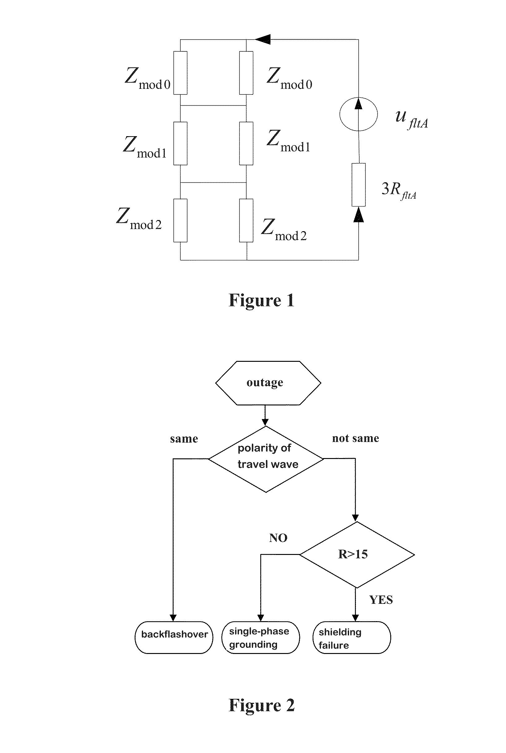
[0071]Table 2 shows that phase B is opposite in polarity against AC phases, from which it can be preliminarily concluded that the outage is a shielding failure or a line fault. The current change rate R of phase B is 46.2, which is smaller than 150, and therefore, it is determined to be a single-phase grounding fault.

[0072]Inspection shows that in the 500 kV A line has a right ground wire broken between tower 35 and 36. The broken wir...

example 2

[0073]The 500 kV XX has a total length of 148.440 km. One day an outage occurs on phase A. The waveform of the travelling wave detected by the fault detectors is shown on FIG. 5, with the wave front characteristic parameters thereof shown on Table 3.

TABLE 3Wave Front Characteristic Parametersof Anther Fault Travelling Wave.AmplitudeHalf waveCurrent changephasepolarity(A)length (us)rate R (A / us)A−396910.5378.00B+12988.9145.84C+13098.9147.08

[0074]Table 3 shows that phase A is opposite in polarity against the BC phases, from which it can be preliminarily concluded that a shielding failure or line fault has occurred. The current change rate of phase A is 378, bigger than 150, and therefore it is a shielding failure. Inspection shows that along the 500 KV OTL, the glass insulator and the grading ring of jumper of phase A in one of the towers have discharge burns, the inspection findings confirms the conclusion drawn from the embodiment.


PUM


Abstract

A method for identifying a lightning fault of an overhead transmission line (OTL) comprising determining a polarity of a travelling wave of each of three ABC phases subsequent to a single phase outage of the OTL. If the polarity of each phase is the same, the outage is a lightning fault and its type a back flashover; if not the same, proceed to the second step to determine a current change rate R of the fault phase. If R is larger than a threshold value, the outage is a lightning fault and its type a shielding failure; otherwise, the outage is a single-phase grounding fault. A system for identifying the lightning fault which comprises successively at least a group of fault detectors, a wireless communication module, a remote monitoring master station which adopts the above method to determine the fault type of the overhead transmission line.

Description

CROSS-REFERENCE TO RELATED APPLICATIONS[0001]The subject application claims priority on Chinese Patent Application No. 201410816946.5 filed on Dec. 24, 2014. The contents and subject matter of the Chinese priority application are incorporated herein by reference.FIELD OF INVENTION[0002]The present invention relates to fault identification in the overhead transmission line, particularly, method and system for identifying a lightning fault and its type in the overhead transmission line.BACKGROUND ART[0003]Direct lightning stroke is the main cause for the overhead transmission line (OTL) fault as shown in the operation record in China and other countries. The direct lightning stroke may be categorized into the shielding failure and back flashover. When the lightning bypasses a shielding wire and directly hits the OTL, the incident is called a shielding failure. When the lightning hits the shielding wire or the tower top, if the grounding resistance is very high and the electric potenti...

Claims


Application Information

Patent Timeline
IPC IPC(8): G01R31/02G01R31/12
CPCG01R31/12G01R31/021G01R29/0842G01R31/085G01R31/1272G01R31/58
Inventor LIU, YADONGSHENG, GEHAOQIAN, YONGHU, YUEJIANG, XIUCHEN
Owner SHANGHAI JIAO TONG UNIV
Why Eureka
Try Eureka