Metal-jet x-ray tube

a technology of x-ray tube and metal jet, which is applied in the direction of discharge tube main electrode, x-ray tube target material, x-ray tube target and convertor, etc., can solve the problems of power density, inability to electrostatically focus the electron beam in magnetic fields of such strength, and too high power loss for given luminous intensities. achieve the effect of increasing light generation efficiency

Active Publication Date: 2016-06-30
SIEMENS HEALTHCARE GMBH
View PDF0 Cites 0 Cited by
  • Summary
  • Abstract
  • Description
  • Claims
  • Application Information

AI Technical Summary

Benefits of technology

[0007]By way of example, the dissolution may be brought about in the form of an alloy or a mixture. In contrast to previous metal jet x-ray tubes, the dissolution enables physically relatively thick but electron-optically thin anodes with a large specific energy absorption capacity. Overall, the metal jet may have the easily realizable cylinder form with a diameter of the order of the electron beam diameter, e.g. 10 to 100 μm, but the metal jet may nevertheless have sufficient electron-kinetic transparency. The mixture or the alloy should have a low melting point in order to enable the liquid jet formation. The improved energy absorption capacity of the anode material reduces the necessary anode beam velocity and / or enables a higher power deposition and hence a higher luminance of the focal spot.
[0013]It was furthermore found to be advantageous to have a further vacuum path downstream of the anode component for the not yet completely decelerated electrons of the electron beam, in which further vacuum path there is deceleration of the electrons, at least approximately to standstill.
[0014]If this decelerating of the electrons is carried out together with an energy recuperation provision, the light generation efficiency is increased in an advantageous manner.

Problems solved by technology

In stationary or rotary anode tubes, or else metal jet x-ray tubes, there is the problem of the power density at the point of incidence of the electron beam on the anode component.
There, too high power losses are generated for given luminous intensities and focal spot luminances.
Moreover, strong background magnetic fields, for example caused in conjunction with magnetic resonance imaging scanners, cause a problem.
It is impossible to electrostatically focus the electron beam in magnetic fields of such strength.
In view of the focal spot power deposition, and also in view of the efficiency, the complete deceleration is a disadvantageous process.

Method used


Image

  • Metal-jet x-ray tube
  • Metal-jet x-ray tube
  • Metal-jet x-ray tube

Examples


Embodiment Construction

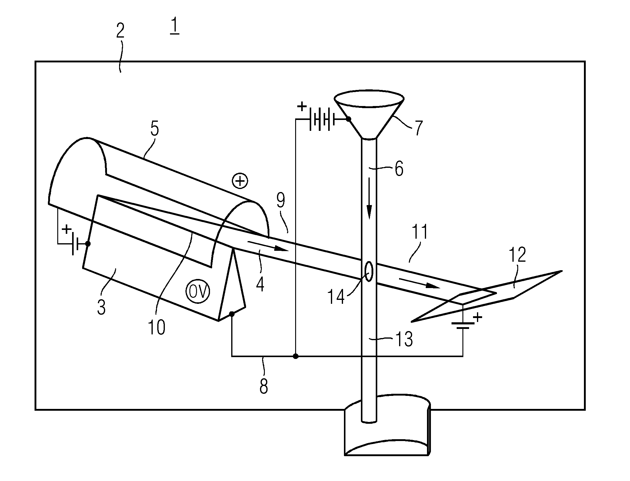
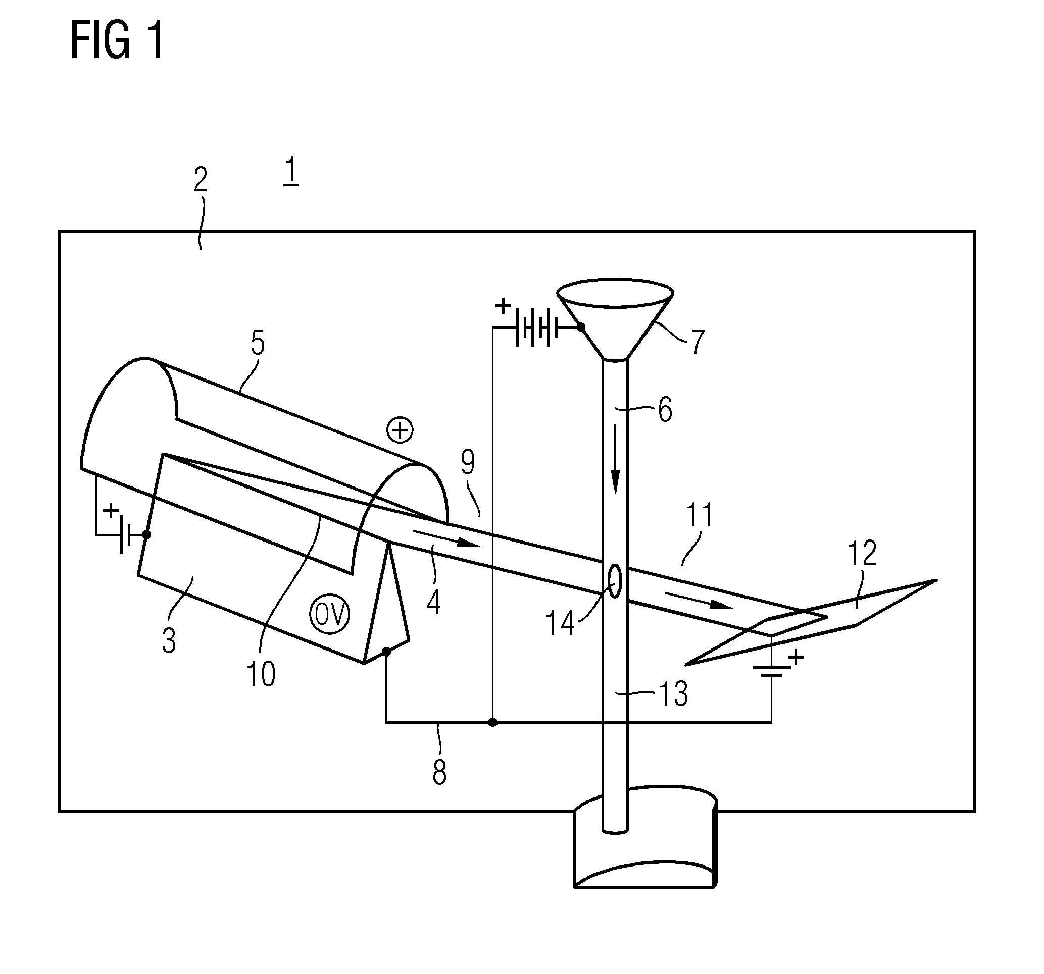
[0019]FIG. 1 depicts a metal jet x-ray tube 1 including a vacuum chamber 2. A cathode component 3 is arranged in the vacuum chamber 2. The cathode component 3 serves to extract an electron beam 4. Moreover, a provision 5 for causing the extraction of the electron beam 4 from the cathode component 3 is provided in the vacuum chamber 2. Furthermore, provision is made in the vacuum chamber 2 for an anode component 7 formed by a liquid metal jet 6. The metal jet 6 is the target for the emitted electron beam 4 of the cathode component 3. A provision 8 serves for accelerating the electron beam 4 emitted by the cathode component 3 in the direction and with the target of the anode component 7, at least within a vacuum path 9.

[0020]The metal jet 6 is realized as a thin metal jet, to the extent that the electrons of the electron beam 4 are only partly decelerated by the metal jet 6. The cathode component 3 has a cathode knife edge 10 such that the cathode component 3 may also be referred to a...


PUM


Abstract

A metal jet x-ray tube is proposed, that is affected less than conventional tubes by the problem of the power density at the point of incidence of the electron beam on the anode component. To this end, the metal jet x-ray tube provides a metal jet as an anode component that is so thin that this metal jet only partly decelerates an electron beam incident thereon. Moreover, the metal jet of the anode component is at least embedded or dissolved in a single second material that passes electrons relatively well and is heat absorbing.

Description

[0001]This application claims the benefit of DE 102014226814.1, filed on Dec. 22, 2014, which is hereby incorporated by reference in its entirety.FIELD[0002]The invention relates to a metal jet x-ray tube in accordance with the preamble of claim 1.BACKGROUND[0003]In stationary or rotary anode tubes, or else metal jet x-ray tubes, there is the problem of the power density at the point of incidence of the electron beam on the anode component. There, too high power losses are generated for given luminous intensities and focal spot luminances. Moreover, strong background magnetic fields, for example caused in conjunction with magnetic resonance imaging scanners, cause a problem. It is impossible to electrostatically focus the electron beam in magnetic fields of such strength.[0004]The problem of maintaining the solid or liquid aggregate state of the anode material in the focal point of the electron beam in rotation anode tubes and in metal jet x-ray tubes is solved by virtue of the mate...

Claims


Application Information

Patent Timeline
Patent Type & Authority Applications(United States)
IPC IPC(8): H01J35/08H01J35/06
CPCH01J35/08H01J2235/082H01J35/06H01J35/24H01J35/064H01J35/116H01J1/16H05G2/005
Inventor HEID, OLIVER
Owner SIEMENS HEALTHCARE GMBH
Why Eureka
Try Eureka