
Utility scale renewable energy system controls for ramp-rate, voltage, and frequency management

a renewable energy system and ramp rate technology, applied in the field of renewable energy system control of ramp rate, frequency and voltage, can solve the problems of voltage problem, difficult and more expensive transportation of fossil fuels to small islands for electricity generation, undesirable voltage and frequency fluctuations in the distributed power system,

Inactive Publication Date: 2016-06-30
EATON INTELLIGENT POWER LTD
View PDF5 Cites 38 Cited by
  • Summary
  • Abstract
  • Description
  • Claims
  • Application Information

AI Technical Summary

Benefits of technology

The patent describes a renewable energy system connected to a point of interconnection in an electrical distribution system. It includes multiple renewable energy sources, each with an inverter that combines with the others to output power. There is also an energy storage device connected to an inverter, which works together with the renewable energy sources. The system has a control system that regulates the voltage and provides control for ramp rate and real power output of the system. This allows for efficient and effective control of the renewable energy system.

Problems solved by technology

However, it is getting harder and more expensive to transport such fossil fuels to small islands for electricity generation.
However, solar PV systems and wind generation systems produce intermittent, variable power because the harvesting of the solar or wind energy varies with environmental factors such as cloud coverage, wind speed, etc.
The intermittency of such renewable energy sources and the long distribution lines typically associated therewith often leads to undesirable voltage and frequency fluctuations in the distributed power system.
The frequency problem is less severe for large utilities but the voltage issue exists.
However, on small stand-alone grids such as those present on small islands for electricity generation, these fluctuations may lead to severe power quality issues leading to brown-outs, load shedding and, in extreme cases, complete shutdown of the generation and distribution system.

Method used


Image

  • Utility scale renewable energy system controls for ramp-rate, voltage, and frequency management
  • Utility scale renewable energy system controls for ramp-rate, voltage, and frequency management
  • Utility scale renewable energy system controls for ramp-rate, voltage, and frequency management

Examples


Embodiment Construction

[0017]Directional phrases used herein, such as, for example, left, right, front, back, top, bottom and derivatives thereof, relate to the orientation of the elements shown in the drawings and are not limiting upon the claims unless expressly recited therein.

[0018]As employed herein, the statement that two or more parts are “coupled” together shall mean that the parts are joined together either directly or joined through one or more intermediate parts.

[0019]As employed herein, the term “number” shall mean one or an integer greater than one (i.e., a plurality).

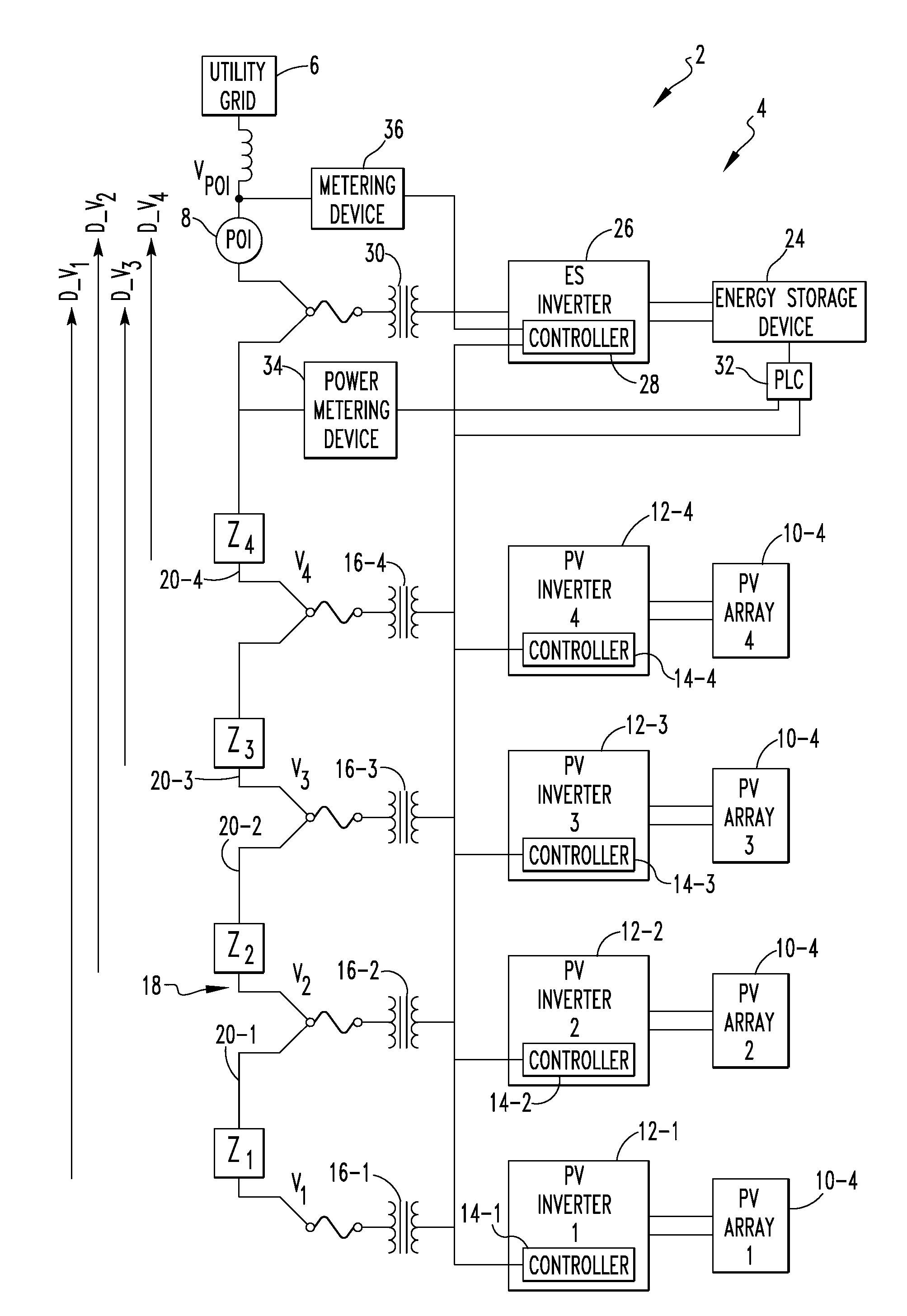
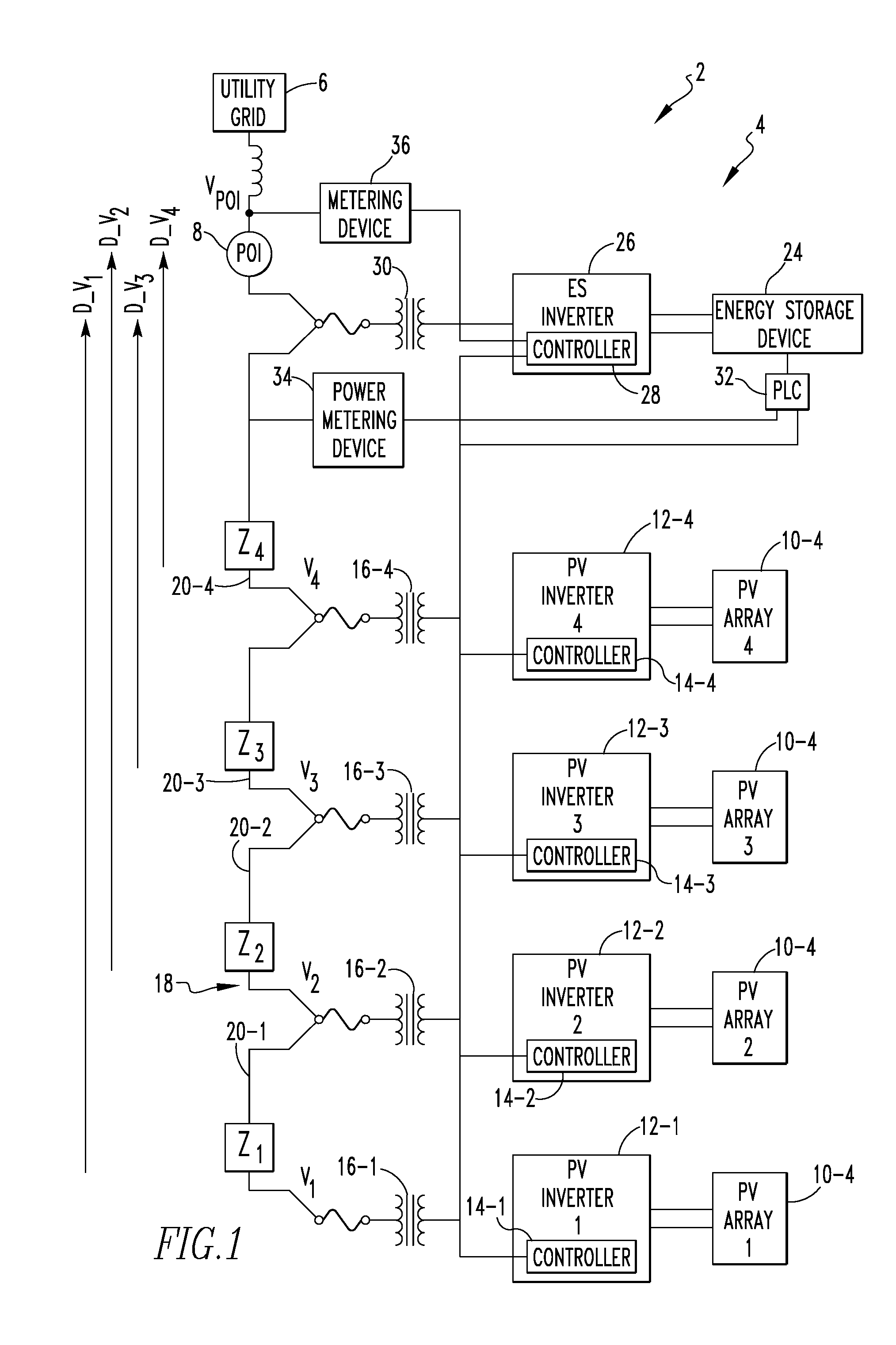
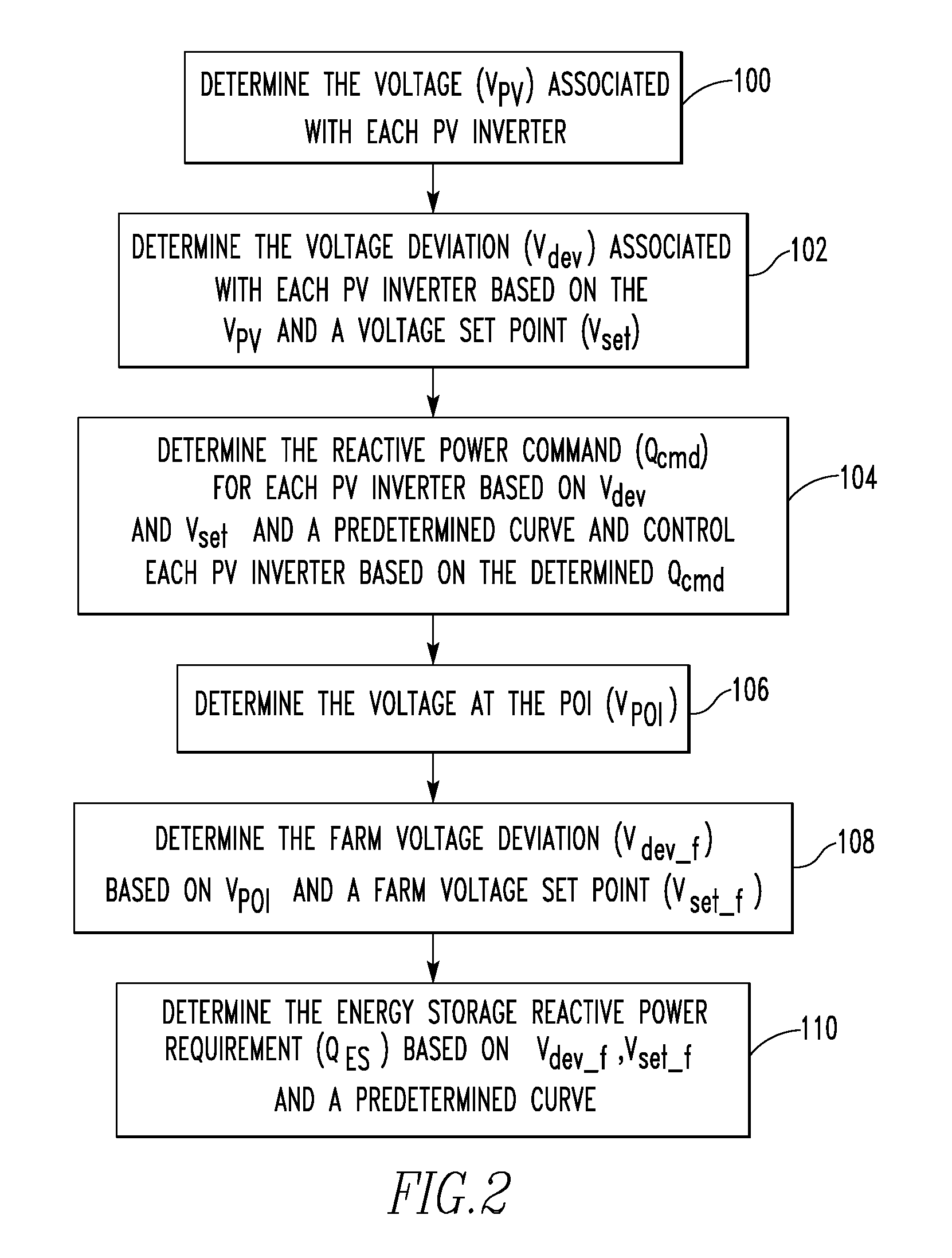
[0020]FIG. 1 is a schematic block diagram of an electrical distribution system 2 according to an exemplary embodiment of the disclosed concept. Electrical distribution system 2 includes a renewable energy system 4 that is interconnected with a utility grid 6 at a point of interconnection (POI) 8 (also referred to as a point of common coupling (PCC)). As described in greater detail herein, in the non-limiting exemplary embodiment...


PUM


Abstract

An energy system includes renewable energy sources each including an inverter. The renewable source inverters are coupled to a distribution line in a manner wherein power combines additively. The system also includes an energy storage source including an energy storage inverter coupled to the distribution line between the point of interconnection and the renewable source inverters. Finally, a control system is structured to: (i) control a voltage at the point of interconnection by controlling a renewable source reactive power output by the renewable source inverters and an energy storage reactive power output by the energy storage inverter, and (ii) provide power ramp rate control for the renewable energy system by controlling at least one of a renewable source real power output by each of the renewable source inverters and a first energy storage real power output by the energy storage inverter.

Description

BACKGROUND[0001]1. Field[0002]The disclosed concept relates generally to the generation and distribution of electricity by systems employing renewable energy sources, and, in particular, to a system and method for controlling and managing power ramp rates, frequencies and voltages in a renewable energy system that is to be interconnected with an existing electric power network (or electrical grid).[0003]2. Background Information[0004]The major resources for generating electricity on small islands (e.g., without limitation, Puerto Rico) have traditionally been in the form of fossil fuels, such as oil, coal, and natural gas. However, it is getting harder and more expensive to transport such fossil fuels to small islands for electricity generation. As a result, many small islands, like Puerto Rico, have looked to increase their utilization of utility connected renewable energy sources, such as solar photovoltaic (PV) systems and wind generation systems (commonly referred to as solar fa...

Claims


Application Information

Patent Timeline
Patent Type & Authority Applications(United States)
IPC IPC(8): H02J3/38H02J3/28
CPCH02J3/28H02J3/383H02J3/16Y02E70/30H02J2300/10H02J2300/20H02J2300/24H02J3/381Y02E10/56Y02E40/30H02J3/50
Inventor BHAVARAJU, VIJAYFU, QIANGFAMILIANT, YAKOV L.THOMPSON, CHRISTOPHER S.
Owner EATON INTELLIGENT POWER LTD
Learn More