
Optical system for producing uniform illumination

a technology of optical system and uniform illumination, applied in the field of optical system, can solve the problems of colour artifacts, non-uniform intensity of collimators, difficult to alleviate all, etc., and achieve the effects of improving illumination efficiency, reducing illumination performance, and improving optical system performan

Inactive Publication Date: 2016-07-07
SIGNIFY HLDG BV
View PDF24 Cites 10 Cited by
  • Summary
  • Abstract
  • Description
  • Claims
  • Application Information

AI Technical Summary

Benefits of technology

This patent is about a new optical system that can improve the uniformity of illumination on a target, even if the light source is non-uniform. The optical system uses multiple lenslets instead of a single set of lenses, which helps to achieve better performance. The system also includes a total internal reflection surface that improves the efficiency of illumination. This new optical system can be used in various applications, such as lighting or imaging, without adding any additional optical elements. Overall, this patent introduces a new way to achieve better lighting results using advanced optical techniques.

Problems solved by technology

It is however problematic to compensate for spatial and / or intensity variations in intensity and / or colour of the light sources used, which is critical when producing uniform illumination.
Typical problems encountered for instance when using an optical system in the form of a standard total internal reflection (TIR) collimator are 1) Colour over angle variation of a light source, leading to colour at different off axis angles in the far field, 2) Colour over position variations of a light source, which also leads to colour artifacts, and 3) Strong non-uniformities in the intensity of the collimator when using an arrays of light sources having dark regions (i.e. regions not producing light) between them.
However, it is challenging to alleviate all the problems mentioned above utilizing the collimator of U.S. 2013 / 0058103, especially if the light source varies strongly in luminance over position.
As a result a uniform illumination may be provided, but at the same time the beam angle of the light leaving the optical system is increased which hinders collimation of the light and reduces control of the light distribution.

Method used


Image

  • Optical system for producing uniform illumination
  • Optical system for producing uniform illumination
  • Optical system for producing uniform illumination

Examples


Embodiment Construction

[0041]The present invention will now be described more fully hereinafter with reference to the accompanying drawings, in which currently preferred embodiments of the invention are shown. This invention may, however, be embodied in many different forms and should not be construed as limited to the embodiments set forth herein; rather, these embodiments are provided for thoroughness and completeness, and fully convey the scope of the invention to the skilled person.

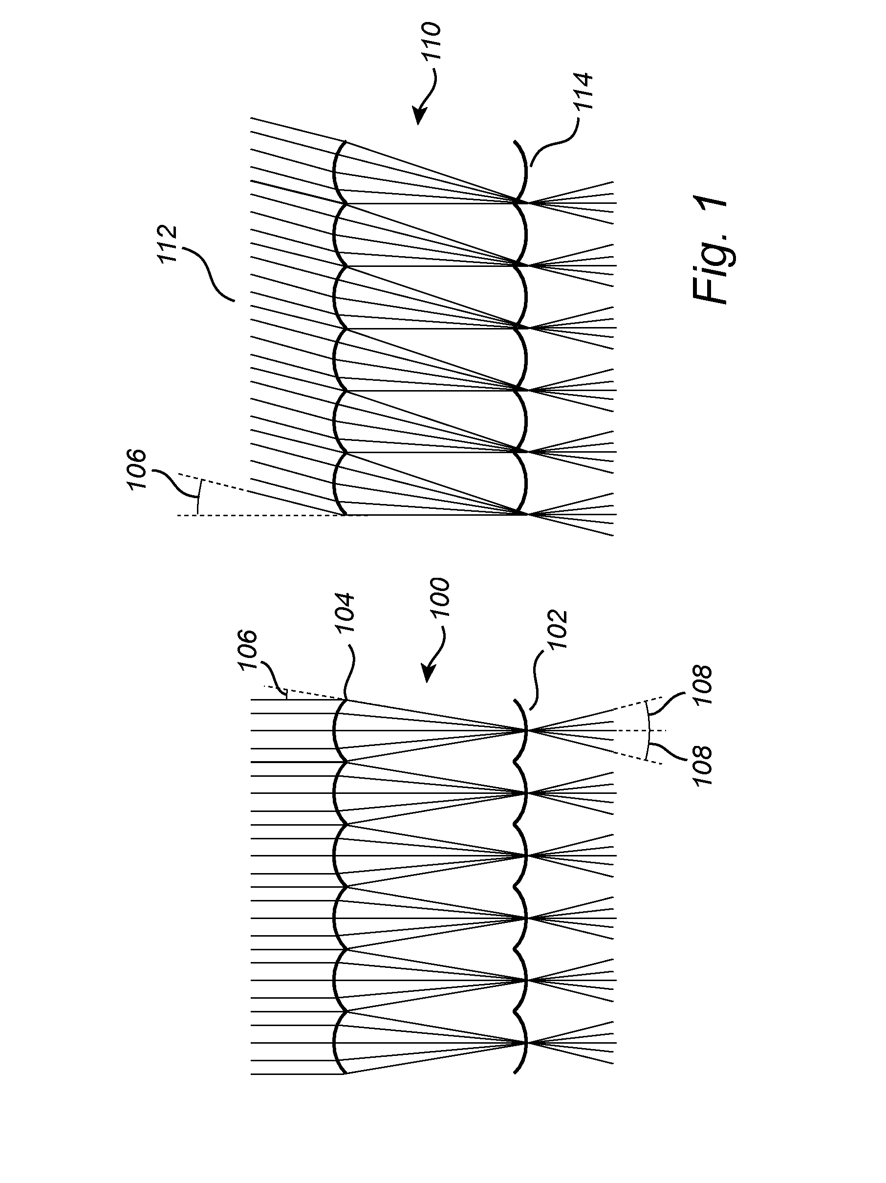
[0042]For an introductory explanation, FIG. 1 shows the cross-section of an elemental integrator 100 comprising a front lenslet array 102 and an identical but oppositely oriented rear array 104, separated by a distance equal to their focal length. Assuming that the aberrations are weak, all rays impinging on the array 104 with half angle 106 from the vertical direction are ideally coupled with all the rays exiting the array 102 within a half angle 108, which equals angle 106. This angle 106 (and 108) is given by the half-an...


PUM


Abstract

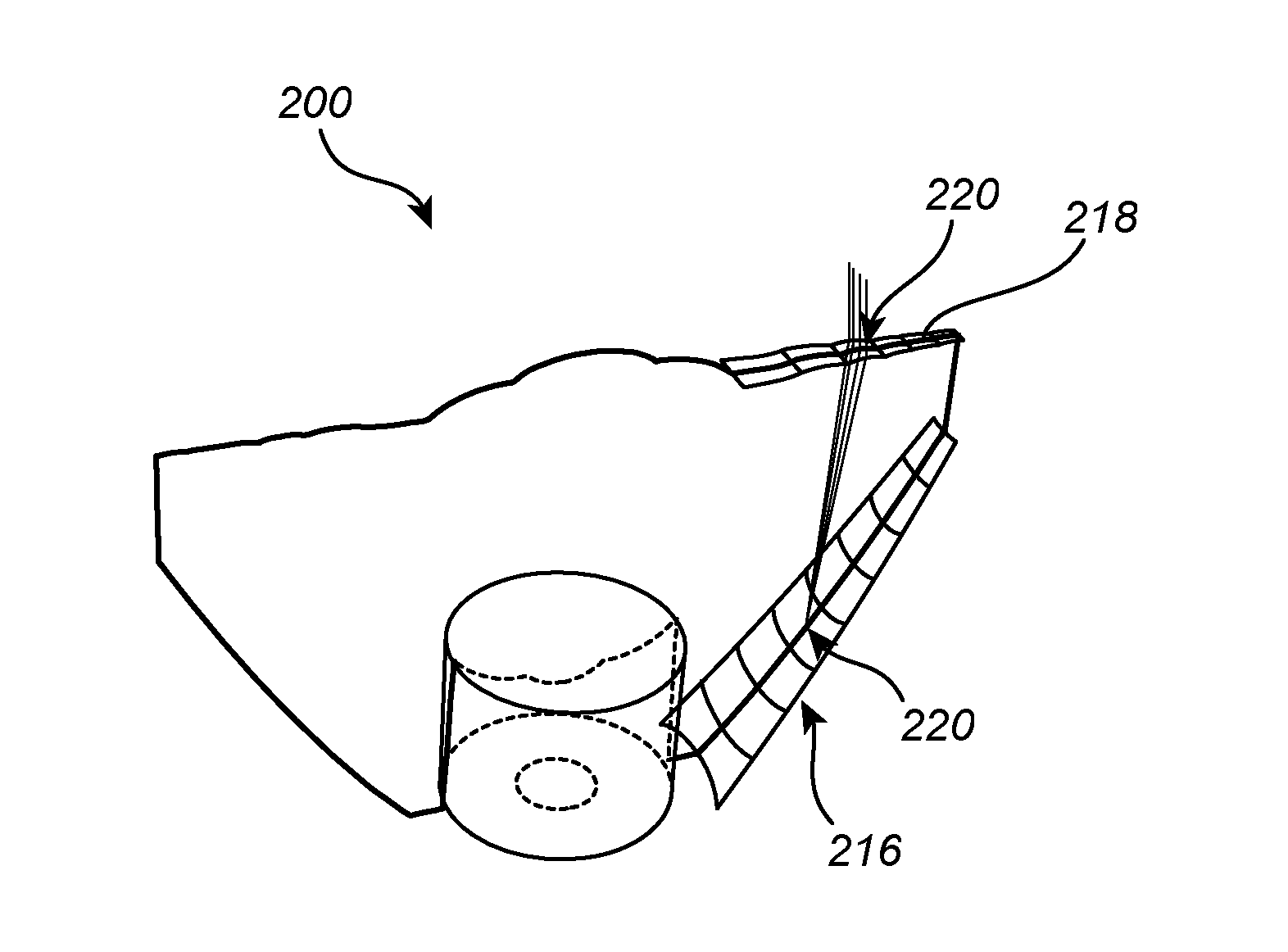
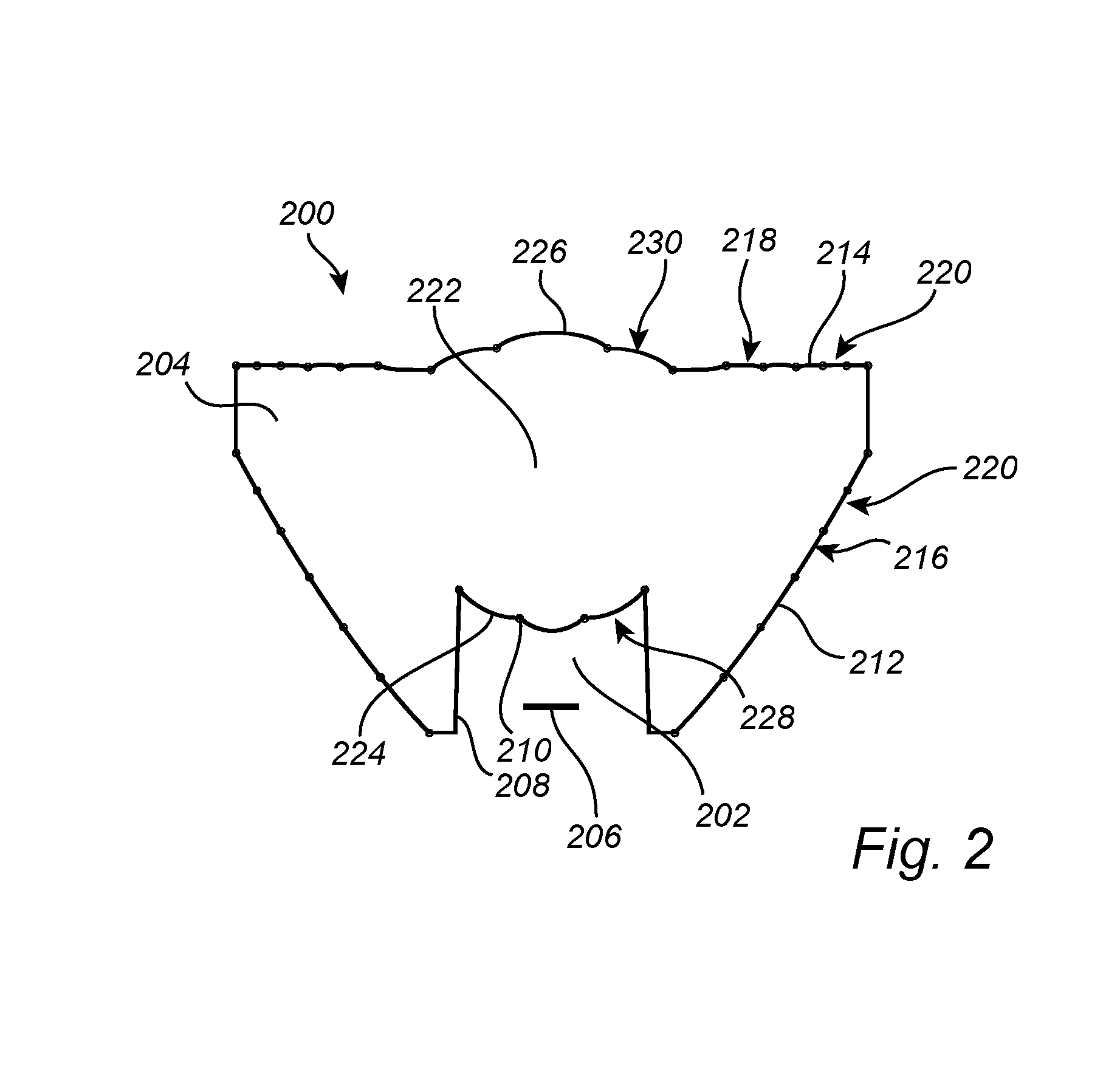
An optical system for producing uniform illumination on a target, comprising a lens body (204), a recess (202) formed on a bottom side of the lens body (204) at a central region thereof accommodating a light source arranged in an integration zone (206), the recess (202) having a side entry surface (208) and a central entry surface (210), a total internal reflection surface (212) provided at a side surface of the lens body (204), wherein the total internal reflection surface (212) comprises a plurality of first lenslets (216); and an exit surface (214) provided at a top side of the lens body (204), the exit surface (314) comprising a plurality of second lenslets (218), wherein each of the first lenslets (216) forms a pair (220) with each of the second lenslets (218), wherein the first lenslet (216) of the pair (220) focuses light from the integration zone (206) upon the second lenslet (218) of the pair (220), and wherein the second lenslet (218) of the pair (220) focuses the target upon the first lenslet (216) of the pair (220), such that the lens (200) produces uniform illumination on the target.

Description

FIELD OF THE INVENTION[0001]The present invention relates to optical systems and in particular to an optical lens for producing uniform illumination on a target.BACKGROUND OF THE INVENTION[0002]The ability to control focusing and distribution of light is critical in order to provide efficient illumination. Many optical systems employ one or more optical elements to achieve a desired light distribution and / or desired illumination uniformity. Depending on situation and requirements various light sources are employed, including incandescence, fluorescence and solid state based light sources. The design of the optical system typically varies depending on the light source used. It is however problematic to compensate for spatial and / or intensity variations in intensity and / or colour of the light sources used, which is critical when producing uniform illumination. Typical problems encountered for instance when using an optical system in the form of a standard total internal reflection (TI...

Claims


Application Information

Patent Timeline
Patent Type & Authority Applications(United States)
IPC IPC(8): F21V13/04F21V7/00F21V5/04F21V7/04
CPCF21V13/04F21V7/048F21V7/0091F21Y2105/001F21V5/045F21Y2101/02F21V7/0066F21V5/004F21Y2115/10F21Y2105/10G02B19/0028G02B19/0061G02B27/0905
Inventor DROSS, OLIVER
Owner SIGNIFY HLDG BV
Learn More