Discontinuous fluidic systems for point-of-care analyte measurement

a fluidic system and analyte technology, applied in the field of analyte detection, can solve the problems of increasing affecting the detection accuracy of analyte, so as to increase the time and complexity of the operation, and improve the sensitivity of the detection.

Active Publication Date: 2016-07-07
FANNIN INNOVATION STUDIO LLC +1
View PDF9 Cites 22 Cited by
  • Summary
  • Abstract
  • Description
  • Claims
  • Application Information

AI Technical Summary

Benefits of technology

[0031]In certain embodiments, magnetic particles are coated with analyte, thereby converting the sandwich immunoassay into a competitive immunoassay.
[0036]In certain embodiments, in order to ensure adequate separation of the particles for maximum exposure to the solvent, the magnet is moved at a very deliberate speed such that: the magnet moves faster than the speed of the magnetic particles in solution, thereby moving ahead; then, the speed of the magnet is reduced to allow the magnetic particles to catch up. As the particles move to the new position of the magnet, the ones that are closer to the magnet move earlier, thus ensuring that all the particles move at different speeds, and hence spread out in the solution. Clumping or aggregation of particles reduces the surface area exposed to the solution, and in embodiments wherein this differential speed is employed, this ensures that the particles do not move as an aggregate. A variety of speeds and stop times of the magnet can be used to get this effect.

Problems solved by technology

Unfortunately, immunoassays performed in a laboratory environment necessitate delays between sample collection and completion of the test.
Additionally, many healthcare environments lack dependable or available laboratory testing facilities or knowledge of laboratory testing methods, necessitating a point-of-care immunoassay device that is rapid, simple to use, and produces quantitative results.
However, washing increases both the time and complexity of the operation, requiring either expert handling or significant automation cost and complexity.
However, absence of washing during the flow limits the sensitivity and range of the detection process.
Currently, there are no methods to do an accurate, quick, cheap, hand-held, point-of-use immunoassay.

Method used


Image

  • Discontinuous fluidic systems for point-of-care analyte measurement
  • Discontinuous fluidic systems for point-of-care analyte measurement
  • Discontinuous fluidic systems for point-of-care analyte measurement

Examples


Embodiment Construction

is given below.

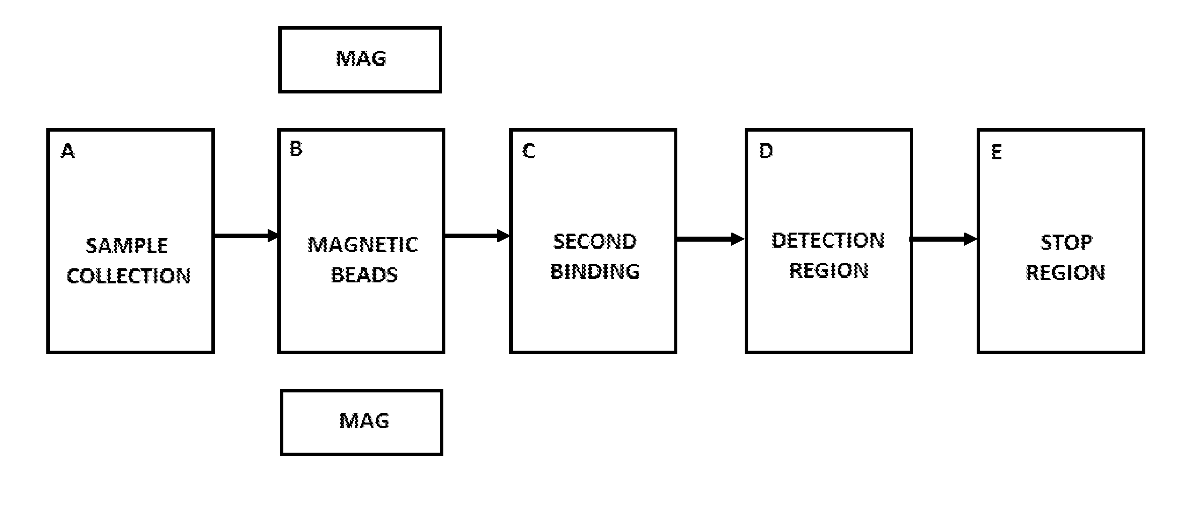
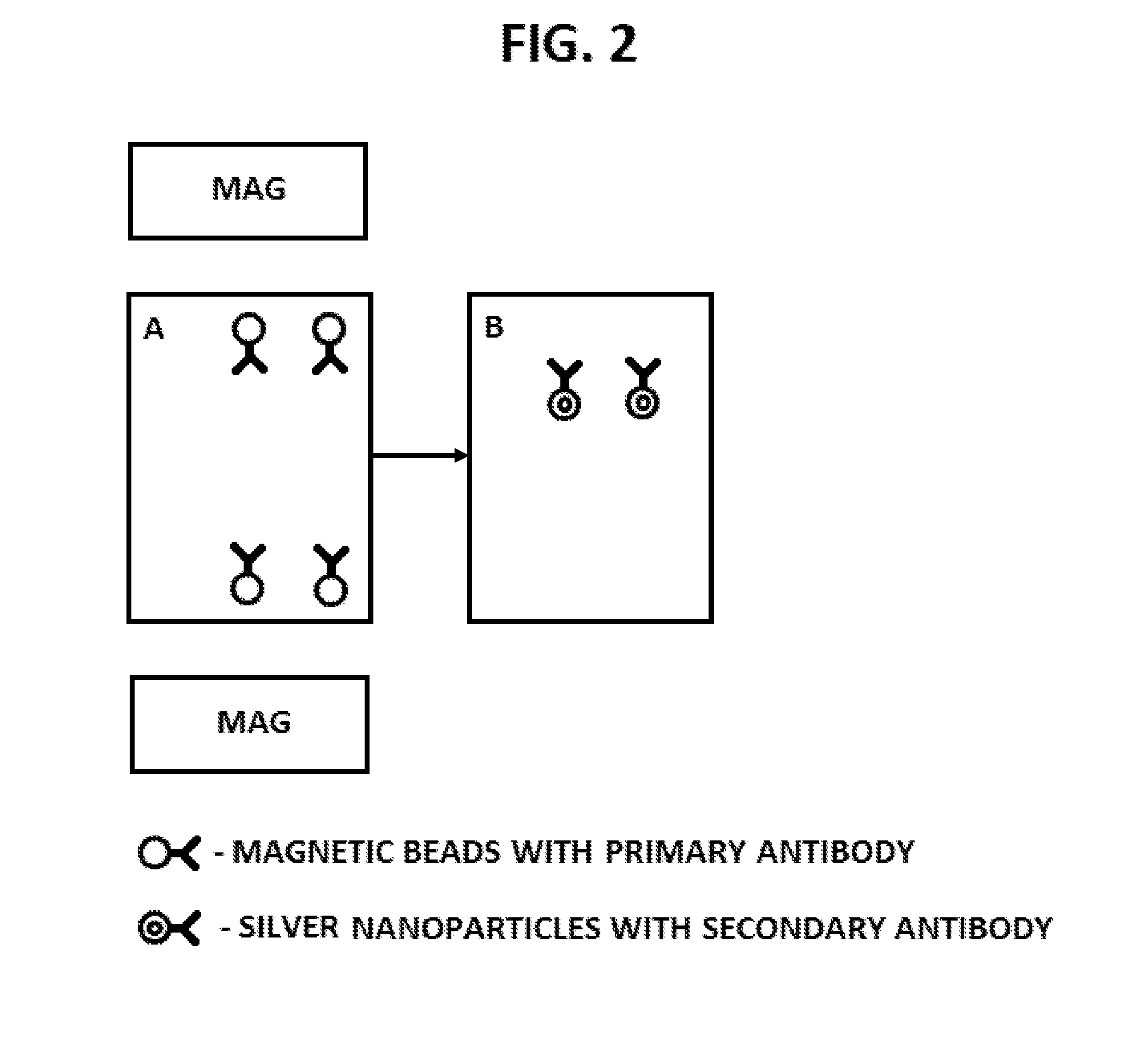
[0025]In one embodiment, there is a method of detecting and quantifying the amount of analyte in a solution using particles that are moved under the influence of an external magnetic field across different regions of a device. In a specific embodiment, the particles are coated with one or more binding agents. In some cases, the binding agents are antibodies that specifically bind to the analyte being detected. In particular embodiments, one of the regions inside the device comprises nanoparticles in suspension coated with a second variety of antibodies (detecting antibodies), which also bind to the analyte, and a third region that contains a detecting chemical, all the regions being separated from one another. In particular cases, the nanoparticles in the second region are made of silver and the detecting region comprises hydrogen peroxide. In certain aspects, the detecting region comprises a dye, such as one whose bleaching under the influence of decomposing hydrogen...


PUM

PropertyMeasurementUnit
diameteraaaaaaaaaa
internal diameteraaaaaaaaaa
magnetic fieldaaaaaaaaaa

Abstract

Disclosed herein are systems and methods for using the controlled movement of magnetic particles using controlled magnetic fields in a fluidic device containing separated fluidic regions to detect analytes in solution by immunoassay, such as an enzyme-linked immunosorbant assay (ELISA) for various medical and scientific applications. In order to achieve sequential exposure to the different chemical environments required in an immunoassay, magnetic particles are driven through fluid-containing chambers separated by air-gaps that may take the form of air bubbles or small open-air separations, for example. Externally controlled magnets coupled to actuators draw the flow of magnetic particles through air-liquid interfaces produced by microfluidic surface tension at the air-gap, washing the particles.

Description

[0001]This application claims priority to U.S. Provisional Patent Application Ser. No. 61 / 932,200, filed Jan. 27, 2014, which is incorporated by reference herein in its entirety.BACKGROUND[0002]1. Technical Field[0003]Embodiments of the field of the disclosure include at least medical devices, medical diagnostics, immunology, cell biology, and molecular biology. In specific embodiments, the disclosure relates to the detection of analyte concentration in solutions prepared from bodily fluids or laboratory samples. The methods and devices in this disclosure are particularly useful for point-of-care medical and laboratory testing in a variety of medical or scientific applications.[0004]2. Background of the Technology[0005]The present invention relates to a method of detecting analyte concentration based on moving magnetic particles through multiple fluid environments, which are not in significant fluid communication, and are separated by gaseous separations. Specifically, the utility o...

Claims


Application Information

Patent Timeline
Patent Type & Authority Applications(United States)
IPC IPC(8): G01N33/543G01N21/78B01L3/00
CPCG01N33/54333B01L3/502715B01L3/502761G01N21/78B01L2200/027G01N2333/908B01L2300/0848B01L2300/021B01L2300/0627B01L2200/0647B01L2300/0861B01L3/502784B01L2200/0668B01L2200/0673B01L2300/0816B01L2300/0858B01L2300/087B01L2400/043
Inventor CHATTERJEE, DEVVARADHACHARY, ATULLLNBECK, LEO
Owner FANNIN INNOVATION STUDIO LLC
Why Eureka
Try Eureka