Magnet arrangement for bone conduction hearing implant

a bone conduction and implant technology, applied in the field of medical implants, can solve the problems of affecting the normal position of the magnet or the whole implant housing, and damage to adjacent tissue in the patient,

Active Publication Date: 2016-07-07
MED EL ELEKTROMEDIZINISCHE GERAETE GMBH
View PDF4 Cites 3 Cited by
  • Summary
  • Abstract
  • Description
  • Claims
  • Application Information

AI Technical Summary

Benefits of technology

[0036]Although various exemplary embodiments of the invention have been disclosed, it should be apparent to those skilled in the art that various changes and modifications can be made which will achieve some of the advantages of the invention without departing from the true scope of the invention.

Problems solved by technology

One problem with implantable hearing prosthesis systems arises when the patient undergoes Magnetic Resonance Imaging (MRI) examination.
The external magnetic field from the MRI may create a torque on the implant magnet, which may displace the magnet or the whole implant housing out of proper position and / or may damage the adjacent tissue in the patient.
The implant magnet may also cause imaging artifacts in the MRI image, there may be induced voltages in the receiving coil, and hearing artifacts due to the interaction of the external magnetic field of the MRI with the implanted device.
Thus, for existing implant systems with magnet arrangements, it is common to either not permit MRI or at most limit use of MRI to lower field strengths.
But the spherical magnet arrangement requires a relatively large magnet much larger than the thickness of the other components of the implant, thereby increasing the volume occupied by the implant.
This in turn can create its own problems.
This is an additional step during implantation in such applications which can be very challenging or even impossible in case of very young children.

Method used


Image

  • Magnet arrangement for bone conduction hearing implant
  • Magnet arrangement for bone conduction hearing implant
  • Magnet arrangement for bone conduction hearing implant

Examples


Embodiment Construction

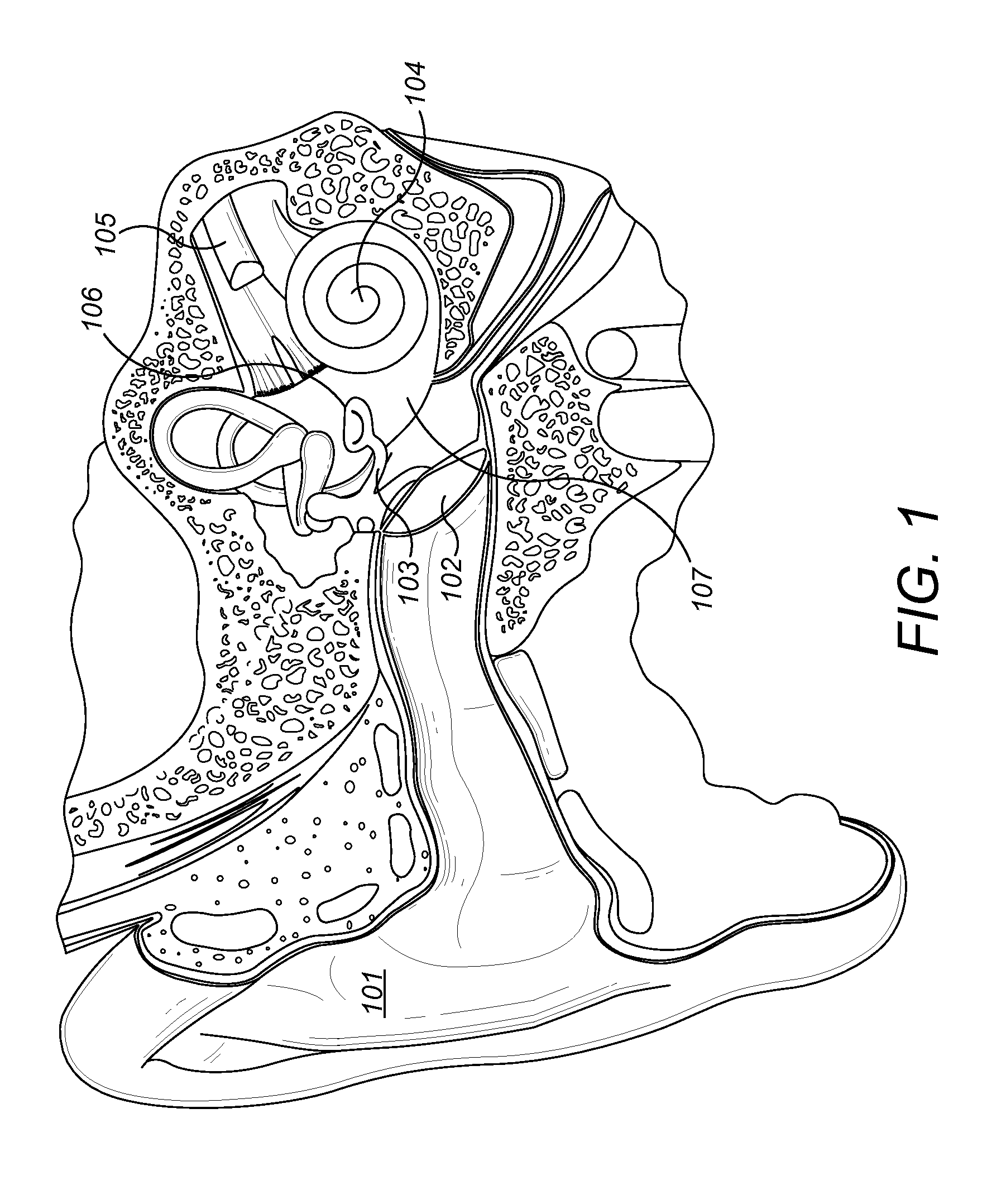
[0023]Embodiments of the present invention are directed to an implantable MRI-compatible magnetic arrangement for a simple cheap and small-size mechanical transducer such as for a bone conduction hearing implant. The magnetic arrangement includes multiple permanent magnets wherein adjacent magnets have opposite magnetic polarities. One or more suspension elements (e.g. silicone, membrane, etc.) resiliently couple adjacent magnets to allow their relative movement. The resulting magnetic transducer thus forms a coupled oscillating system with an external magnetic drive component above the skin of the patient to develop a mechanical stimulation signal to the implant housing surrounding the magnets for delivery by bone conduction of the skull bone as an audio signal to the cochlea of the patient.

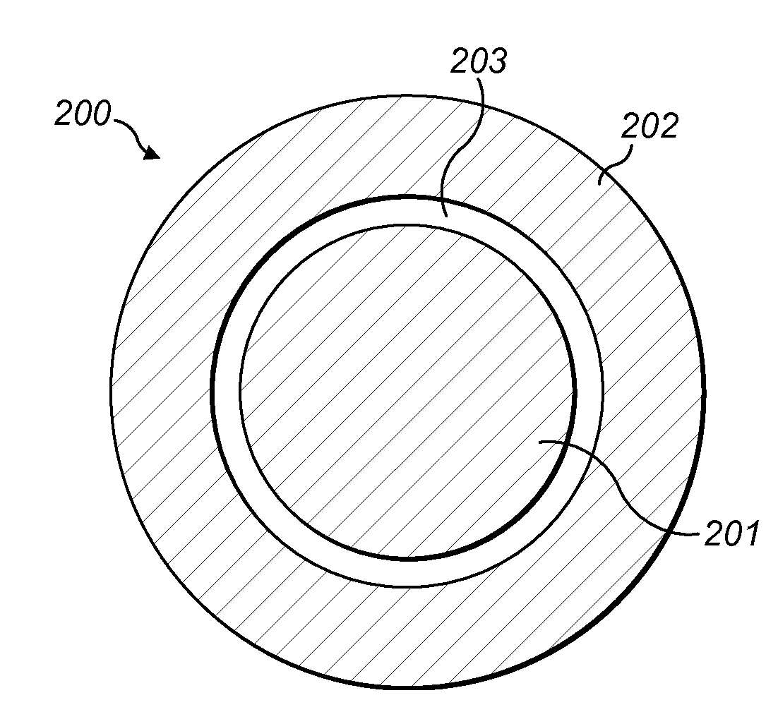
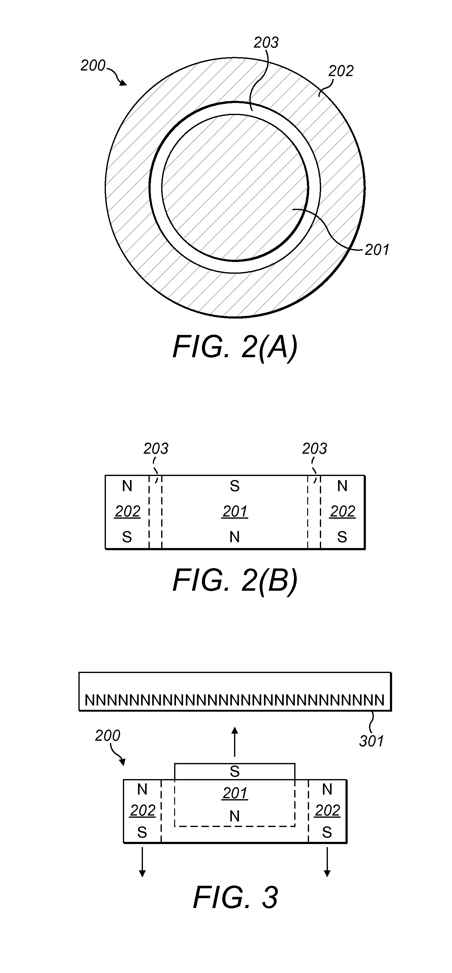
[0024]FIG. 2 A shows a top plant view and FIG. 2B shows a side cross-sectional view of a magnetic arrangement 200 for a hearing implant according to one specific embodiment. An inner cylindrical...


PUM


Abstract

An implantable magnetic transducer arrangement is described for a hearing implant in a recipient patient. An implant housing hermetically encapsulates an interior housing volume and is fixedly attached to skull bone beneath the skin of the patient. A magnetic transducer is located within the housing volume and includes multiple permanent magnets wherein adjacent magnets have opposite magnetic polarities, and one or more suspension elements that resiliently couple adjacent magnets to allow their relative movement. The magnetic transducer forms a coupled oscillating system with an external magnetic drive component above the skin of the patient to develop a mechanical stimulation signal to the implant housing for delivery by bone conduction of the skull bone as an audio signal to the cochlea of the patient.

Description

[0001]This application claims priority from U.S. Provisional Patent Application 61 / 669,161, filed Jul. 9, 2012, and from U.S. patent application Ser. No. 13 / 780,193, filed Feb. 28, 2013, which are incorporated herein by reference.FIELD OF THE INVENTION[0002]The present invention relates to medical implants, and more specifically to a novel transcutaneous auditory prosthetic implant system.BACKGROUND ART[0003]A normal ear transmits sounds as shown in FIG. 1 through the outer ear 101 to the tympanic membrane (eardrum) 102, which moves the ossicles of the middle ear 103 (malleus, incus, and stapes) that vibrate the oval window 106 and round window 107 membranes of the cochlea 104. The cochlea 104 is a long narrow duct wound spirally about its axis for approximately two and a half turns. It includes an upper channel known as the scala vestibuli and a lower channel known as the scala tympani, which are connected by the cochlear duct. The cochlea 104 forms an upright spiraling cone with a...

Claims


Application Information

Patent Timeline
Patent Type & Authority Applications(United States)
IPC IPC(8): H04R25/00
CPCH04R25/00A61N1/08A61N1/3718A61N1/375H04R25/606A61N1/36036A61N1/37518H04R11/02
Inventor NAGL, MARKUSLECHLEITNER, THOMAS
Owner MED EL ELEKTROMEDIZINISCHE GERAETE GMBH
Why Eureka
Try Eureka