Multi-rotor safety shield

a safety shield and multi-rotor technology, applied in emergency equipment, transportation and packaging, toys, etc., can solve the problems of rapid descent and/or uncontrolled flying, human damage, and uas industry cannot develop,

Active Publication Date: 2016-07-14
ROTOR SHIELD LLC
View PDF0 Cites 95 Cited by
  • Summary
  • Abstract
  • Description
  • Claims
  • Application Information

AI Technical Summary

Benefits of technology

[0018]While WO 2015/10554 A1 Giuesppe Santangelo and Skypersonic LLC purports enclosure, it cannot support nor state complete and substantial encasement due to the exposure of the critical Drone components. Furthermore it makes no claim of

Problems solved by technology

The UAS industry cannot develop unless it is proven safe.
Although Drones can be built from lightweight material such as Styrofoam and powered by low speed electrical rotors, modern drones are increasingly built from heavier composite materials, and include complex and high performance power plants which can spin the propellers at velocities between 10,000 and 50,000 RPM's, as an example.
The software shuts down all working rotors which in turn causes rapid descent and/or uncontrolled flying.
Unprotected a carbon fiber blades spinning at 40,000 rpm become a dangerous razor sharp cutting instrument that can lacerate human flesh (as shown in Picture #1) and can cause disastrous or even fatal damage to humans and/or cause disastrous property damage.
Once wood, carbon-fiber, aluminum, or steel or any other metal is employed for commercial or hobbyist use, the danger from the propellers becomes immediate.
Unfortunately, one of the less talked about aspects of drone flight involves malfunctions.
Drones have malfunctioned in a myriad of ways, have become disoriented by lack of communication and have ultimately been lost to the user plummeting from the sky because of multitude of reasons including but not limited to propeller contact, mechanical breakdowns, human error, bad weather, electronic failures, and lost communications.
When the catastrophic failure of any system causes uncontrolled descen

Method used


Image

  • Multi-rotor safety shield
  • Multi-rotor safety shield
  • Multi-rotor safety shield

Examples


first embodiment

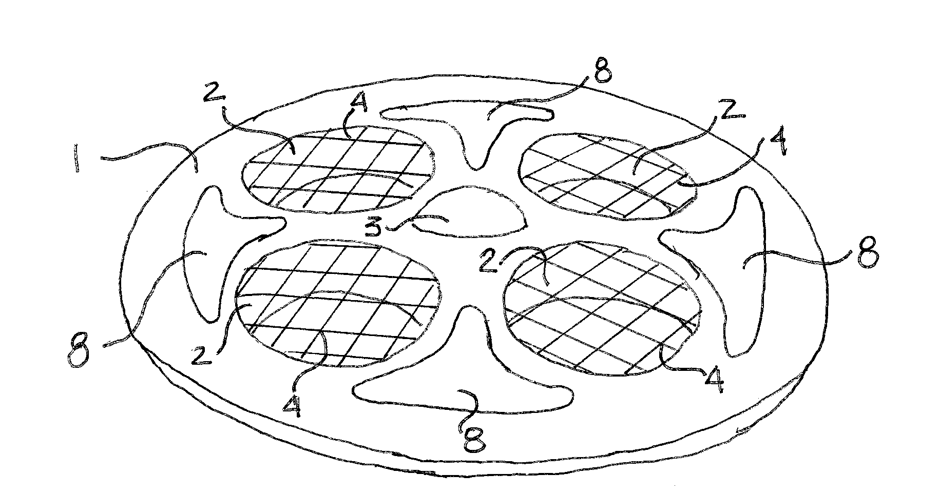
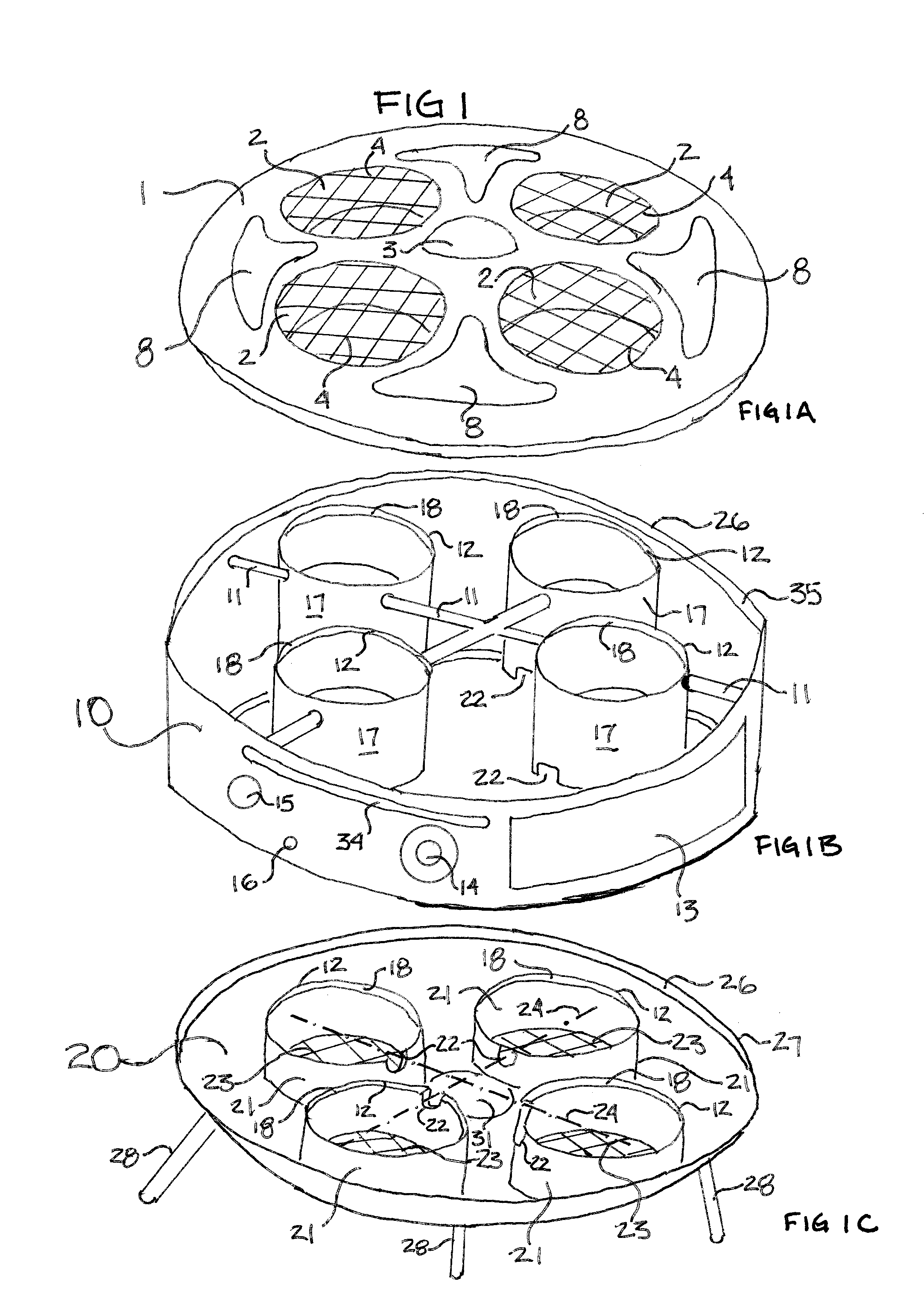
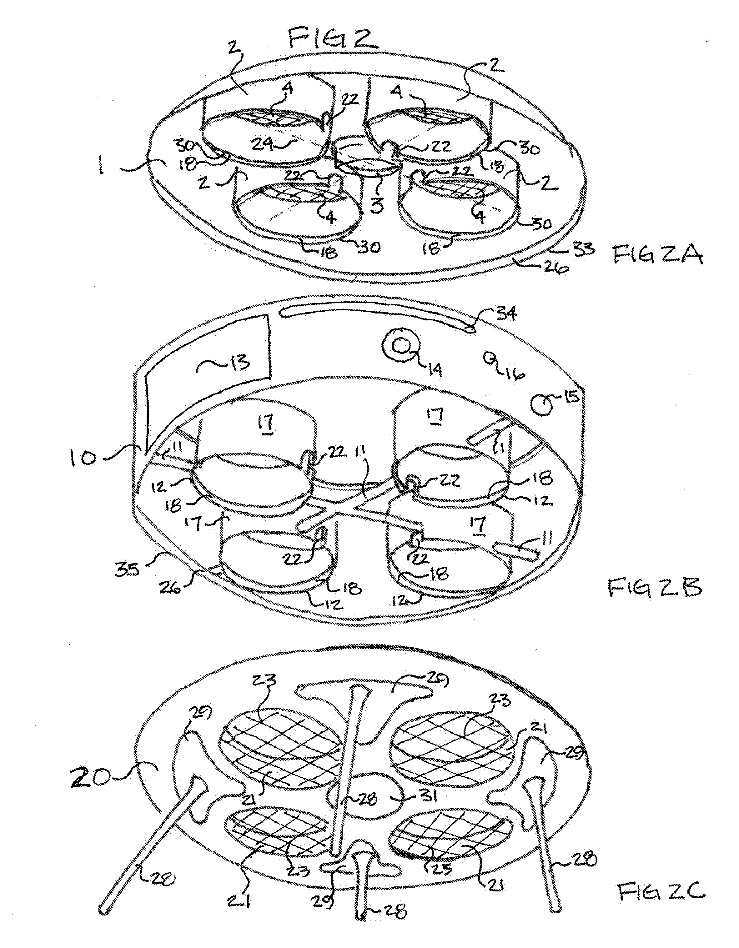
[0046]Now that a basic understanding of the intent and principals of the Multi-Rotor Safety Shield (MRSS) have been described, the following detailed disclosure is provided. As will be known to those of skill in the art, however, the invention is not to be construed as limiting to the following description, as many other shapes, sizes, construction materials and uses are also contemplated.

[0047]In one embodiment the MRSS is a modular system with two primary components 1, 20 and an optional third component 10. The composition of the MRSS is of any variety of thermoformed or machineable plastic including but not limited to ABS, Acetyl, Acrylic, HDPE, PVC, UHMW or PTFE. Composition of the MRSS can also be any variety of metal including but not limited to aluminum, steel, stainless steel, copper, brass, bronze, or lightweight metals and or any future lightweight materials that become available.

[0048]In one embodiment the bottom housing component 20 is any shape or configuration that pro...


PUM


Abstract

The Multi-Rotor Safety Shield (MRSS) provides a complete and substantial encasement system which can be secured about a Drone, protecting a multitude of aircraft components from contact with any outside disturbance and which can protect the sensitive components from dust, water, wind, rain, snow, fingers, toes, appendages of any kind, and atmospheric changes as example, from disabling the Drone and can protect people, places or things from high velocity spinning exposed rotor/propellers. The MRSS provides rigid non-permeable platform for attaching or incorporating additional safety devices as found in the Drone industry (or other industries) resulting in a safety device that completely prevents the loss a Drone due to the catastrophic failure of any Drone system or combination of systems which would typically result in rapid decent, and/or uncontrolled flight. The MRSS makes Drones safe near humans and safe to use around public gatherings, stadium events, accident scenes, disaster search and rescue and disaster relief, and indoors for the security and communications markets among others expanding the availability of Drones to further assist humanity.

Description

CROSS-REFERENCE OF RELATED APPLICATIONS[0001]This application claims the benefit of provisional patent application Ser. No. 62 / 101,201 filed 2015 Jan. 8, by Jason Terry Daniel Attorney for the claimant.FEDERALLY SPONSORED RESEARCH[0002]None.SEQUENCE LISTING[0003]NoneBACKGROUNDPrior Art[0004]The following is a tabulation of some prior art that presently appears relevant:U.S. PatentsPatent NumberKind CodeIssue DatePatentee4,795,1111989 Jan. 3Moller5,575,4381996 Nov. 19McGonigle et al.6,153,9592000 Nov. 28Lorenzo6,270,038B12001 Aug. 7Cycon et al.7,032,861B22006 Apr. 25Sanders, Jr. et al.7,249,732B22007 Jun. 31Sanders, Jr. et al.7,712,701B12010 May 11Ehrmantraut et al.8,328,130B22012 Dec. 11Goosen8,774,982B22014 Jul. 8Oakley et al.8,777,157B22014 Jul. 15Barrett et al.2014 / 0339355A12014 Nov. 20OLM et al.9,004,973B22015 Apr. 14Condon et al.International Patent DocumentsPatent NumberKind CodeIssue DatePatenteeWO2015 / 105554A12015 Jul. 16Santangelo et al.BACKGROUND OF THE INVENTION[0005]Owin...

Claims


Application Information

Patent Timeline
IPC IPC(8): B64C1/06B64C39/02B64D17/78B64C27/08
CPCB64C1/062B64D17/78B64C39/024B64C27/08A63H27/12B64U10/13B64U30/20B64C27/20B64C39/001
Inventor COOPER, ROBERT STANLEY
Owner ROTOR SHIELD LLC
Why Eureka
Try Eureka