Radio frequency filter with cavity structure

a radio frequency filter and cavity structure technology, applied in waveguide devices, basic electric elements, resonators, etc., can solve the problems of large amount of heat produced in view of insertion loss, operation malfunction, and increased processing cost, and achieve the effect of low cost and simple fabrication

Active Publication Date: 2016-07-14
KMW INC
View PDF3 Cites 9 Cited by
  • Summary
  • Abstract
  • Description
  • Claims
  • Application Information

AI Technical Summary

Benefits of technology

[0013]Accordingly, an object of the present disclosure is to provide a radio frequency filter with a cavity structure, for enabling frequency tuning without using a coupling structure of tuning screws and fastening nuts, and even when a relatively large filter is fabricated, facilitating simple fabrication with low cost.
[0014]Another object of the present disclosure is to provide a radio frequency filter with a cavity structure, which can stably compensate for a change in filtering characteristics, caused by a temperature change, and which can be fabricated with relatively low cost.

Problems solved by technology

The technology disclosed in Korea Laid-Open Patent Publication No. 10-2014-0026235 is suitable for a small, lightweight filter structure because it does not adopt the general coupling structure of tuning screws and fastening nuts.
As a result, process cost may be increased.
Especially if a cavity filter is used as a high-power transmission filter, a large amount of heat is produced in view of insertion loss.
As capacitance and inductance are changed due to a change in the distances between components and thus unique characteristics of the filter are changed, operation malfunction may occur.
This problem becomes serious in a resonator structure using a metal resonant rod.
However, it is difficult to compensate the temperature of the radio frequency filter because of the limitations (price and thermal expansion coefficient) of a material applied to the resonant rods of the cavity filter.

Method used


Image

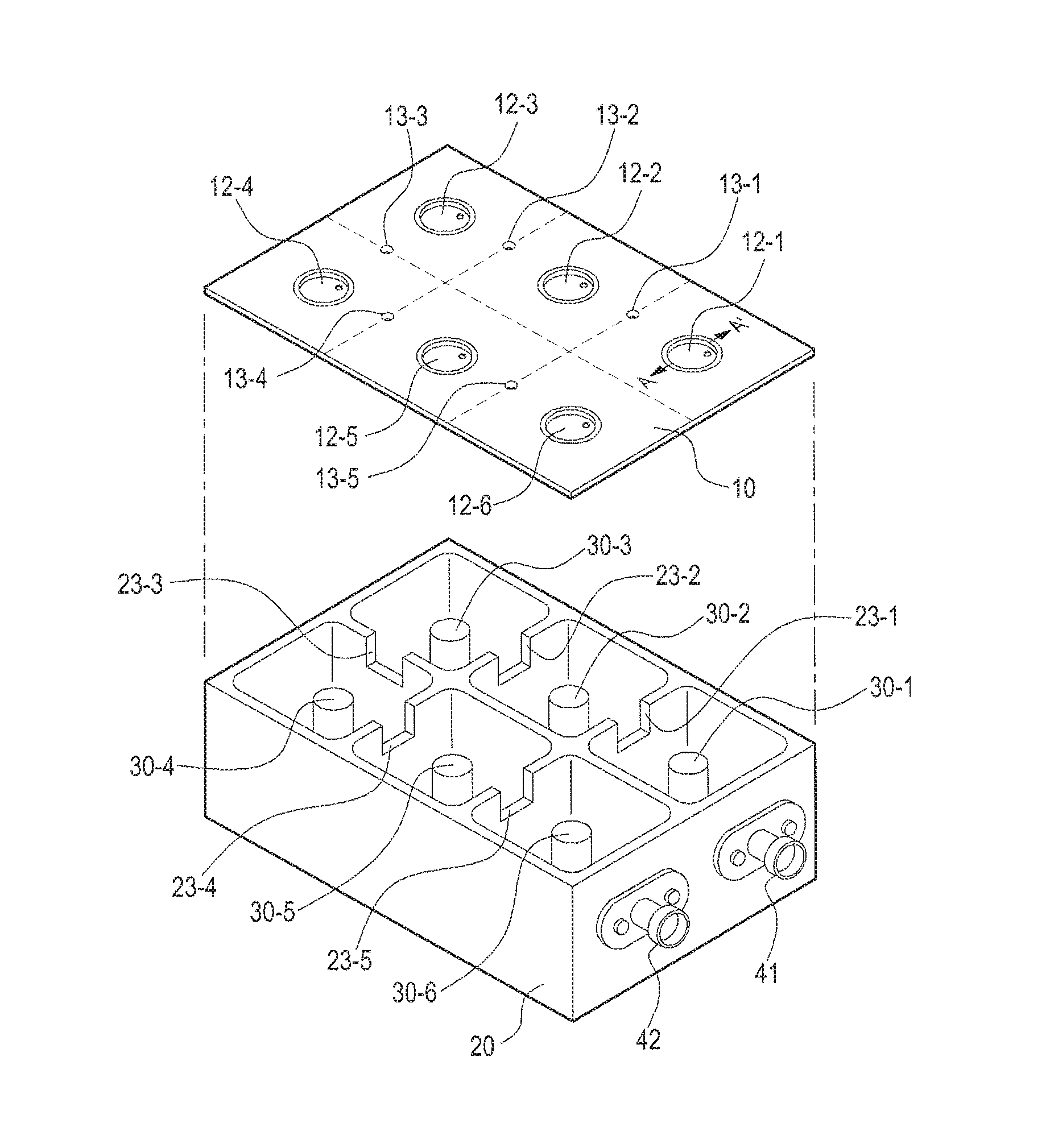
  • Radio frequency filter with cavity structure
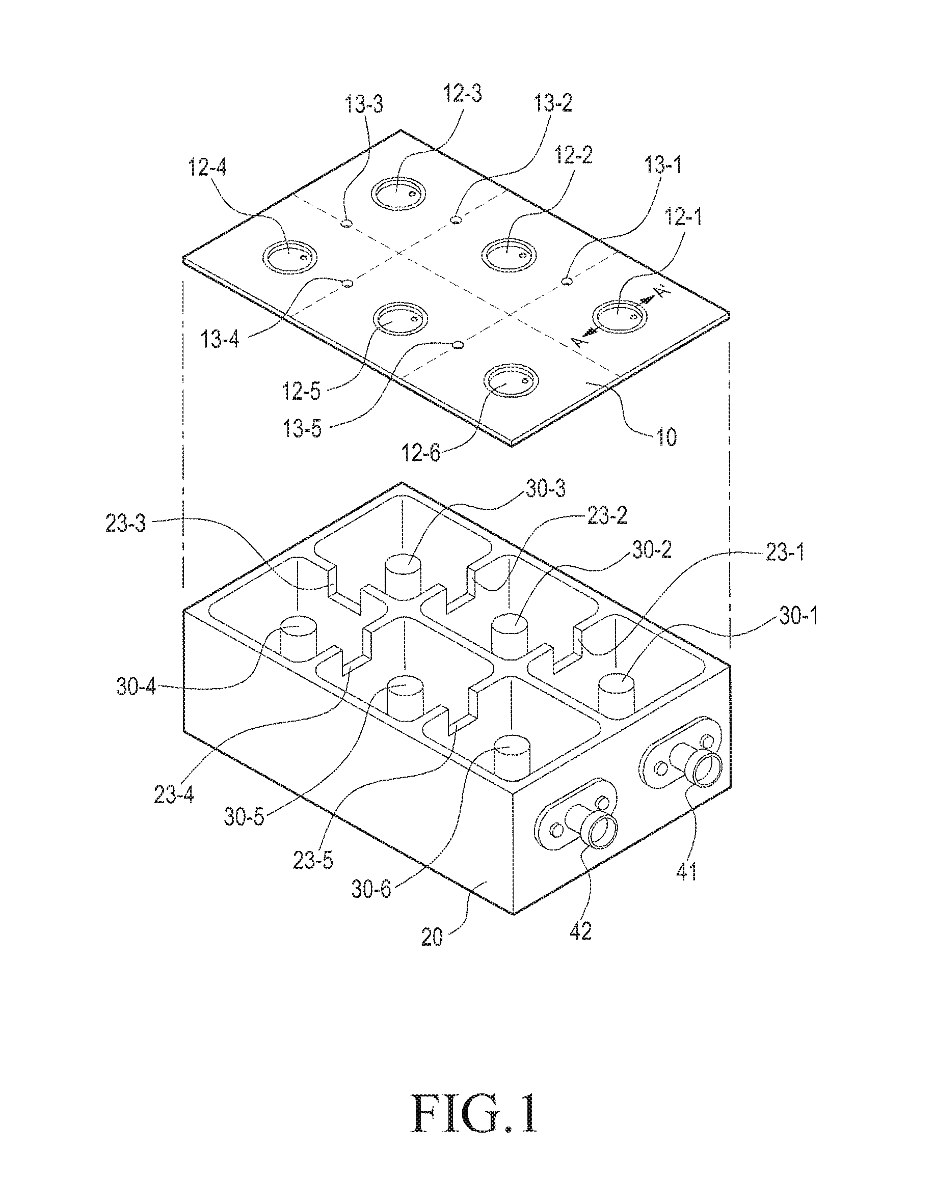
  • Radio frequency filter with cavity structure
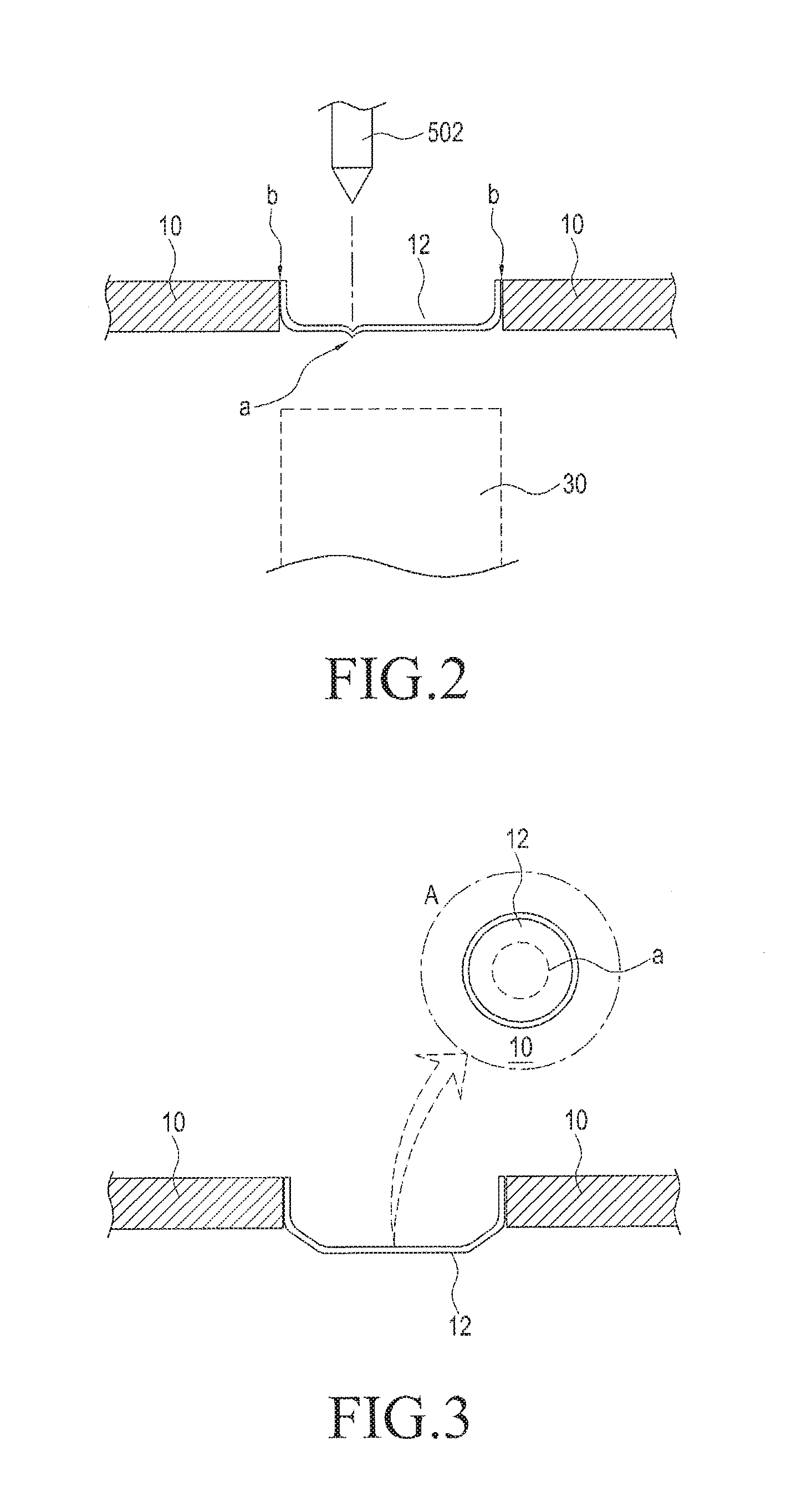
  • Radio frequency filter with cavity structure

Examples


Embodiment Construction

[0026]Reference will now be made in detail to the preferred embodiments of the present disclosure. While the invention will be described in conjunction with exemplary embodiments, it will be understood that present description is not intended to limit the invention to those exemplary embodiments. On the contrary, the invention is intended to cover not only the exemplary embodiments, but also various alternatives, modifications, equivalents and other embodiments, which may be included within the spirit and scope of the invention as defined by the appended claims.

[0027]The terminology used herein is for the purpose of describing particular embodiments only and is not intended to be limiting of the invention. As used herein, the singular forms “a”, “an” and “the” are intended to include the plural forms as well, unless the context clearly indicates otherwise. It will be further understood that the terms “comprises” and / or “comprising,” when used in this specification, specify the prese...


PUM


Abstract

A radio frequency filter with a cavity structure is provided. The radio frequency filter includes a housing having an inner hollow portion to have a cavity and open from one side of the housing, a cover sealing the open side of the housing, and a resonant element disposed inside the hollow housing. A through hole is formed at a part of the cover, corresponding to the resonant element, and a tuning element is installed covering the through hole, for frequency tuning. The tuning element is formed of a material having a different thermal expansion coefficient from a thermal expansion coefficient of a material of the cover.

Description

CROSS REFERENCE TO RELATED APPLICATIONS[0001]This application is a continuation of International Application No. PCT / KR2015 / 010654 filed on Oct. 8, 2015, which claims priority to Korean Application No. 10-2014-0147612 filed on Oct. 28, 2014, which applications are incorporated herein by reference.BACKGROUND[0002]1. Technical Field[0003]The present disclosure relates to an apparatus for processing a wireless signal, for use in a wireless communication system, and more particularly, to a radio frequency filter with a cavity structure, such as a cavity filter.[0004]2. Description of the Related Art[0005]A radio frequency filter with a cavity structure generally includes a plurality of rectangular accommodating spaces, that is, cavities in a metal housing, with a resonant element such as a dielectric resonant (DR) element or a metal resonant rod accommodated in each cavity, to thereby generate ultra-high frequency resonance. In the radio frequency filter with this cavity structure, a co...

Claims


Application Information

Patent Timeline
Patent Type & Authority Applications(United States)
IPC IPC(8): H01P1/205H01P7/04
CPCH01P1/20H01P1/208H01P1/2053H01P7/04H01P1/30H01P1/207H01P1/2138H01P1/202
Inventor PARK, NAM-SHINKIM, JOUNG-HOE
Owner KMW INC
Why Eureka
Try Eureka