Tunable delay circuit and operating method thereof

a delay circuit and delay technology, applied in the field of delay circuits, can solve the problems of affecting the performance of the whole system, unpredictable and uncontrollable, and achieve the effect of relatively long total delay time of tunable delay circuit, and relatively short total delay tim

Active Publication Date: 2016-07-21
MEDIATEK SINGAPORE PTE LTD SINGAPORE
View PDF6 Cites 5 Cited by
  • Summary
  • Abstract
  • Description
  • Claims
  • Application Information

AI Technical Summary

Benefits of technology

[0016]In some embodiments, when the first pass bit has a high logic level and the second pass bit has a high logic level and the third pass bit has a high logic level, a total delay time of the tunable delay circuit is relatively short; when the first pass bit has a low logic level and the second pass bit has a high logic level and the third pass bit has a high logic level, the total delay time of the tunable delay circuit is relatively medium; and when the first pass bit has a low logic level and the second pass bit has a low logic level and the third pass bit has a high logic level, the total delay time of the tunable delay circuit is relatively long.

Problems solved by technology

However, since the driving paths in clock tree circuits often have different lengths, they tend to result in clock skew, and degrade the performance of the whole system.
The different lengths of driving paths may also be caused by on-chip variations (OCV), which are unpredictable and uncontrollable.

Method used


Image

  • Tunable delay circuit and operating method thereof
  • Tunable delay circuit and operating method thereof
  • Tunable delay circuit and operating method thereof

Examples


Embodiment Construction

[0023]In order to illustrate the purposes, features and advantages of the invention, the embodiments and figures of the invention will be described in detail as follows.

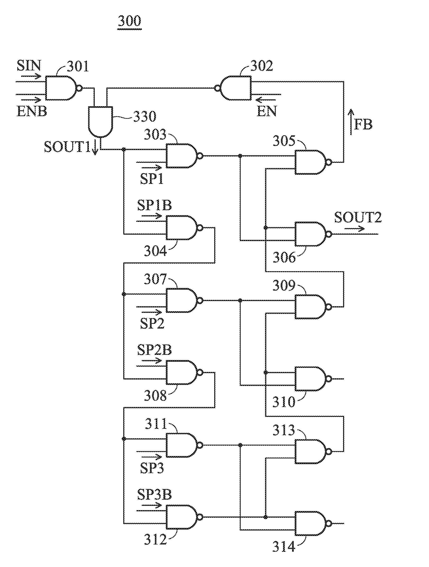
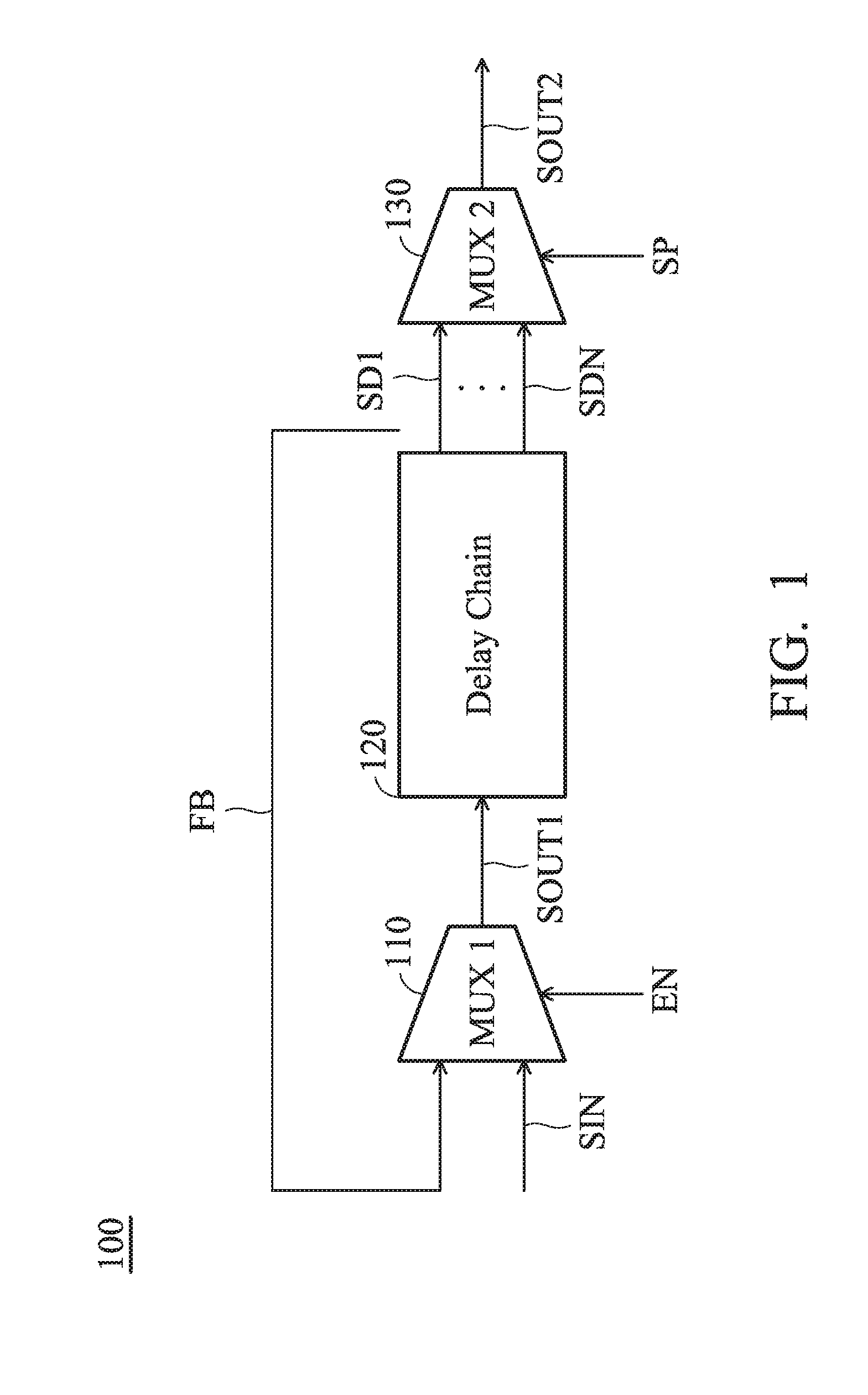
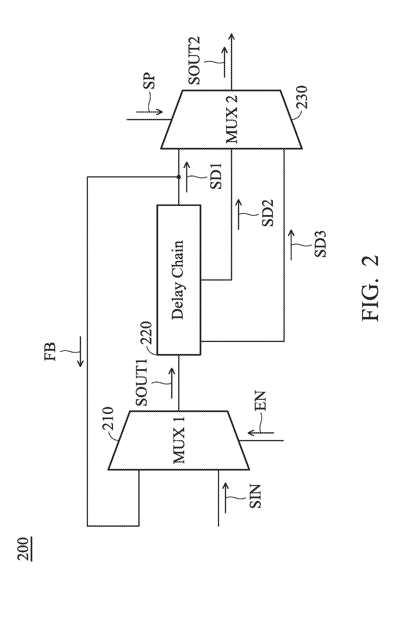
[0024]FIG. 1 is a diagram of a tunable delay circuit 100 according to an embodiment of the invention. The tunable delay circuit 100 may be applied to integrated circuits and configured to compensate for the clock skew, which may be caused by on-chip variations (OCV) and / or different lengths of clock driving paths. As shown in FIG. 1, the tunable delay circuit 100 includes a first multiplexer (MUX 1) 110, a delay chain 120, and a second multiplexer (MUX 2) 130. The first multiplexer 110 is configured to select an input signal SIN or a feedback signal FB as a first output signal SOUT1 according to an enable signal EN. The first output signal SOUT1 is forwarded to the delay chain 120. The delay chain 120 may include multiple cascading delay units (not shown). The delay chain 120 is configured to delay the first output s...


PUM


Abstract

A tunable delay circuit includes a first multiplexer, a delay chain, and a second multiplexer. The first multiplexer selects an input signal or a feedback signal as a first output signal according to an enable signal. The delay chain delays the first output signal for different time periods so as to generate a plurality of delay signals. One of the delay signals is used as the feedback signal. The second multiplexer selects one of the delay signals as a second output signal according to a pass signal.

Description

CROSS REFERENCE TO RELATED APPLICATIONS[0001]This application claims the benefit of U.S. Provisional Application No. 62 / 105,414, filed on Jan. 20, 2015, the entirety of which is incorporated by reference herein.BACKGROUND OF THE INVENTION[0002]1. Field of the Invention[0003]The disclosure generally relates to a delay circuit, and more particularly, to a delay circuit with a tunable and measureable delay time.[0004]2. Description of the Related Art[0005]Clock tree circuits are commonly used in the field of digital circuit design. However, since the driving paths in clock tree circuits often have different lengths, they tend to result in clock skew, and degrade the performance of the whole system. The different lengths of driving paths may also be caused by on-chip variations (OCV), which are unpredictable and uncontrollable. Accordingly, there is a need to design a novel circuit to solve the above problem.BRIEF SUMMARY OF THE INVENTION[0006]In one exemplary embodiment, the disclosure...

Claims


Application Information

Patent Timeline
Patent Type & Authority Applications(United States)
IPC IPC(8): H03K5/13H03K3/03H03K19/20
CPCH03K5/133H03K3/0315H03K19/20H03K19/1737
Inventor WU, YIPINLIU, HENG-MENG
Owner MEDIATEK SINGAPORE PTE LTD SINGAPORE
Why Eureka
Try Eureka