Surface cleaning device

a cleaning device and surface technology, applied in the direction of vacuum cleaners, carpet cleaners, domestic applications, etc., can solve the problems of damage to the floor, poor cleaning performance, and difficulty in controlling the amount of liquid left on the floor

Active Publication Date: 2016-07-28
VERSUNI HLDG BV
View PDF5 Cites 15 Cited by
  • Summary
  • Abstract
  • Description
  • Claims
  • Application Information

AI Technical Summary

Benefits of technology

The patent describes a solution for cleaning surfaces using a squeegee and a new way of liquid transport. The squeegee wipes liquid from the surface and the liquid is absorbed by a cloth in front of the squeegee. The cloth is placed on a porous material that can hold liquid, and a small under-pressure is applied to the reservoir to create a continuous flow of liquid through the cloth and into the reservoir. This design simplifies the appliance and allows for easy cleaning and replacement of the cloth. Additionally, the cloth can be sucked almost completely dry using more under-pressure, making it more hygienic to store the appliance.

Problems solved by technology

The main disadvantage of the bucket and mop principle is that the amount of liquid that remains on the floor is difficult to control.
This can result in a poor cleaning performance when the mop is too dry but even worse, it can result in damage to the floor when the mop is too wet.
The main disadvantage of window cleaning with sponge and squeegee is that the liquid is wiped of the window but is not collected by anything.
But the liquid pick up is very little due to the limitations of absorption of the material.
Consumers see this as a big hassle of wringing the cloth or sponge which results in liquid spillage etc.
A general disadvantage of the above mentioned manual cleaning methods is that the performance over time is not constant.
A mop, cloth or sponge is getting increasingly dry during the cleaning action when releasing liquid to the surface, and is getting increasingly wet during the drying action when absorbing liquid from the surface.
The main issues for the above mentioned system are that a rather big fan / motor must be used to generate sufficient airflow to transport the liquid, that the air and the liquid needs to be separated again and the fan / motor must be suited to handle moist or moist air.
That means that this system is expensive and complex.

Method used


Image

  • Surface cleaning device
  • Surface cleaning device
  • Surface cleaning device

Examples


Embodiment Construction

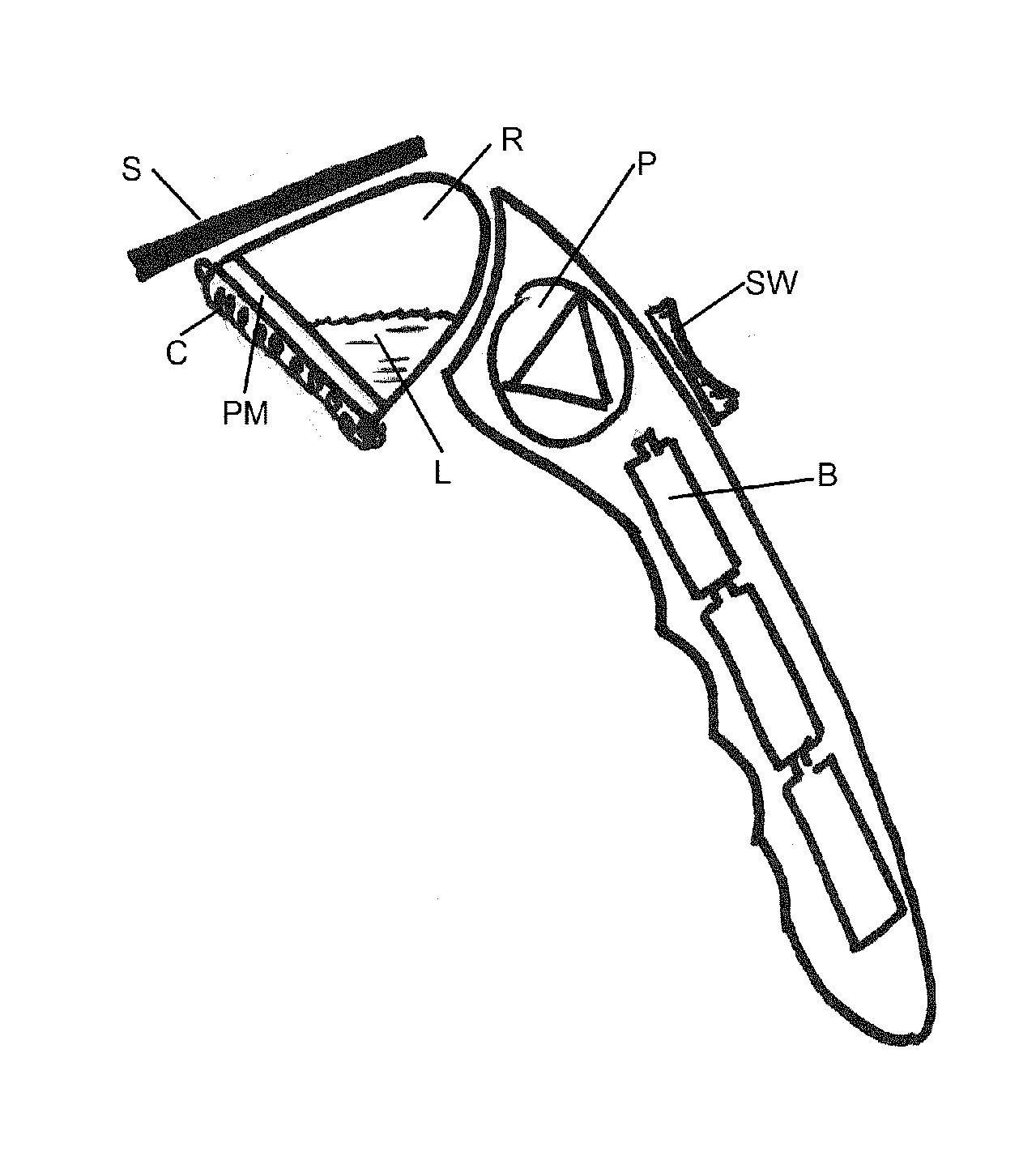
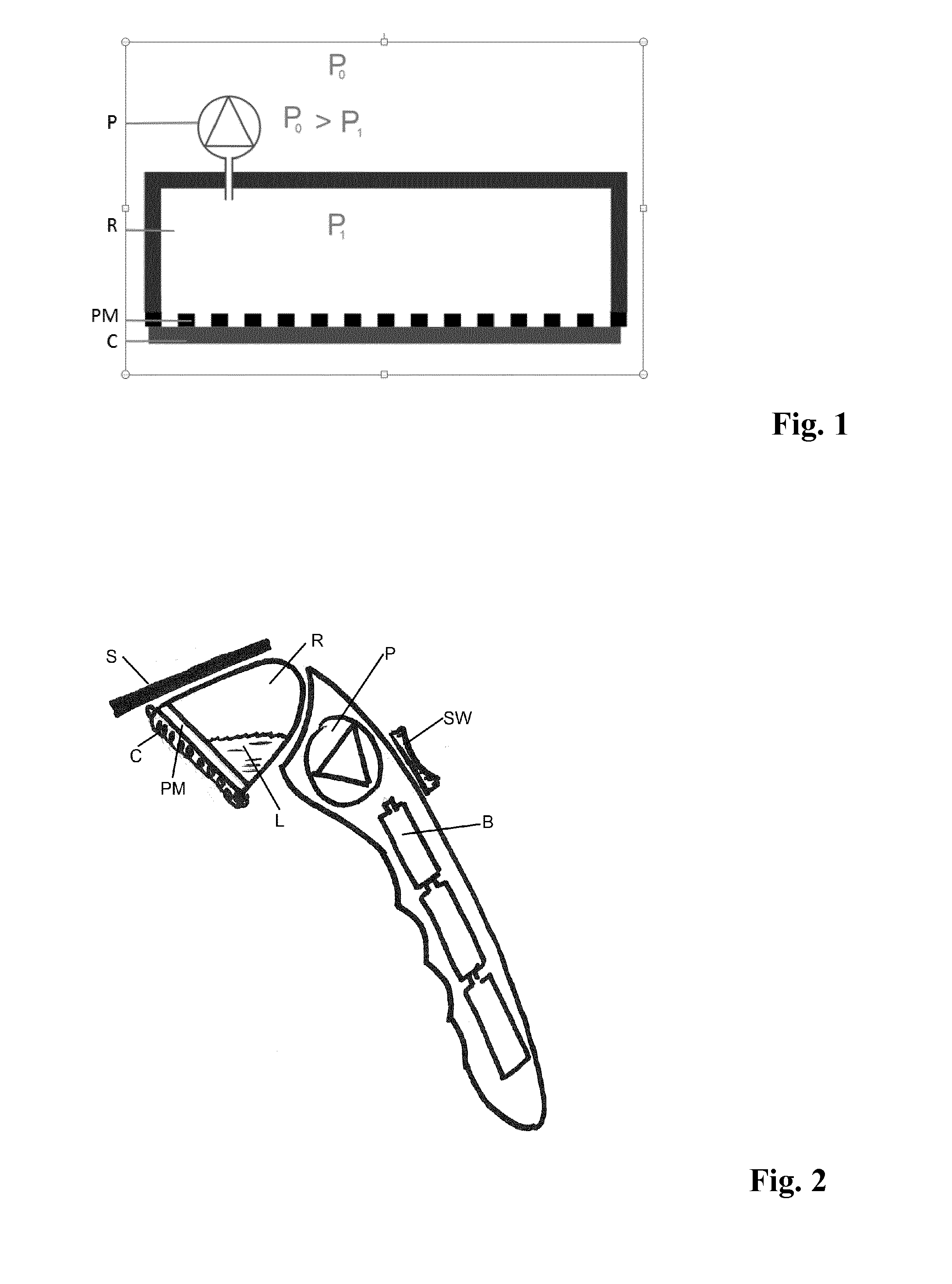
[0022]The essence of the embodiment of FIG. 1 is the porous material PM and the contact area with the cloth C. The porous material PM is preferably hydrophilic, and the pore size is chosen in such a manner that the material has a preference to pass liquid above air when a pressure difference is applied. Tests showed that a pore size between 1 μm and 50 μm is suited for this application.

[0023]The porous material PM may be a plastic sheet having pores. Alternatively, the porous material PM can be a porous polymer with liquid permeable properties as available from Porex Corporation and other porous polymer manufacturers.

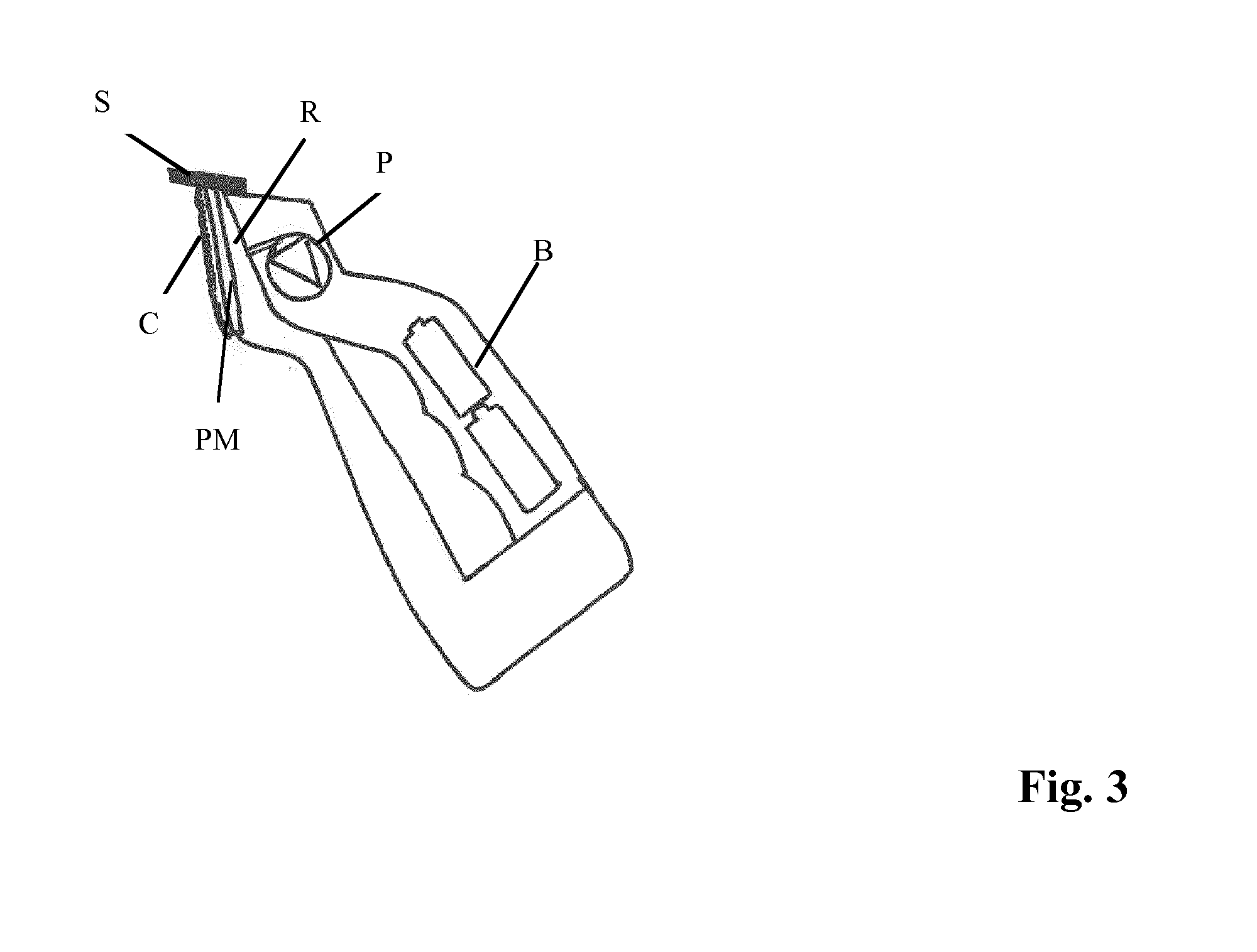
[0024]The porous material PM is a part of the reservoir R or part of a soleplate that is a housing for the cloth or sponge to rest upon. The porous plastic is important as it has two functions:[0025]a. Allow moisture from the cloth C to pass to the reservoir R because of under-pressure;[0026]b. Do not allow the moisture collected in the reservoir R to come out again, i....


PUM


Abstract

Surface cleaning device, comprising a cloth (C) placed on a porous material (PM), a reservoir (R) for collecting liquid absorbed by the cloth (C), and an arrangement (P) for applying under-pressure in the reservoir (R) so as to transfer liquid from the cloth (C) into the reservoir (R). A pore size of the porous material (PM) is between 1 μm and 50 μm.

Description

FIELD OF THE INVENTION[0001]The invention relates to a surface cleaning device.BACKGROUND OF THE INVENTION[0002]U.S. Pat. No. 5,720,078 discloses a suction device for removing liquids from a surface such as a floor. The device includes an air chamber formed from a top and a bottom plate, each of the plates having a respective top and bottom surface. The bottom plate includes a plurality of holes therethrough. The bottom surface of the bottom plate additionally includes fabric adjacent thereto and feet to hold the bottom plate of the device up off the floor to enable fluid to be suctioned through the bottom plate holes and into the chamber via a conventional source of suction. In an embodiment, each of said holes is between 0.030 to 0.250 inches in diameter.[0003]WO 2006 / 091439 discloses a cleaning implement that provides multiple functions useful in cleaning windows and similar surfaces. There is a support head mounting a squeegee blade and (optionally) a scrubber and / or touch-up pa...

Claims


Application Information

Patent Timeline
Patent Type & Authority Applications(United States)
IPC IPC(8): A47L7/00A47L5/24A47L1/15
CPCA47L7/0004A47L5/24A47L1/15A47L1/05A47L11/4044A47L11/408A47L7/0009A47L9/0686
Inventor LUBBERS, MATTHIJS HENDRIKUSKINGMA, PIETER
Owner VERSUNI HLDG BV
Why Eureka
Try Eureka