Needle insertion and retraction arrangment with manually triggered, spring-loaded drive mechanism

a drive mechanism and needle insertion technology, applied in the direction of infusion needles, infusion devices, etc., can solve the problems of presenting a number of risks and challenges for users and healthcare professionals, and achieve the effect of improving the drive mechanism

Inactive Publication Date: 2016-07-28
SANOFI AVENTIS DEUT GMBH
View PDF30 Cites 13 Cited by
  • Summary
  • Abstract
  • Description
  • Claims
  • Application Information

AI Technical Summary

Benefits of technology

[0033]The insertion arrangement has only limited space requirements thus allowing for low profile injection devices with a high wearing comfort. The insertion arrangement achieves high speed needle movements and exact needle guidance thus reducing pain for the patients when inserting and retracting the needle and increasing consumer acceptance and satisfaction. The low part count of the insertion arrangement allows for an increased mechanical robustness and low manufacturing costs. The insertion arrangement is a fault-tolerant system. In the insertion arrangement a single button is used for triggering both needle insertion and needle retraction.

Problems solved by technology

Administering an injection is a process which presents a number of risks and challenges for users and healthcare professionals, both mental and physical.
During manual insertion of an injection needle into an injection site, e.g. the skin of a patient, it may be difficult to avoid tilting and bending of the needle and the insertion may be slow thus causing pain.

Method used


Image

  • Needle insertion and retraction arrangment with manually triggered, spring-loaded drive mechanism
  • Needle insertion and retraction arrangment with manually triggered, spring-loaded drive mechanism
  • Needle insertion and retraction arrangment with manually triggered, spring-loaded drive mechanism

Examples


Embodiment Construction

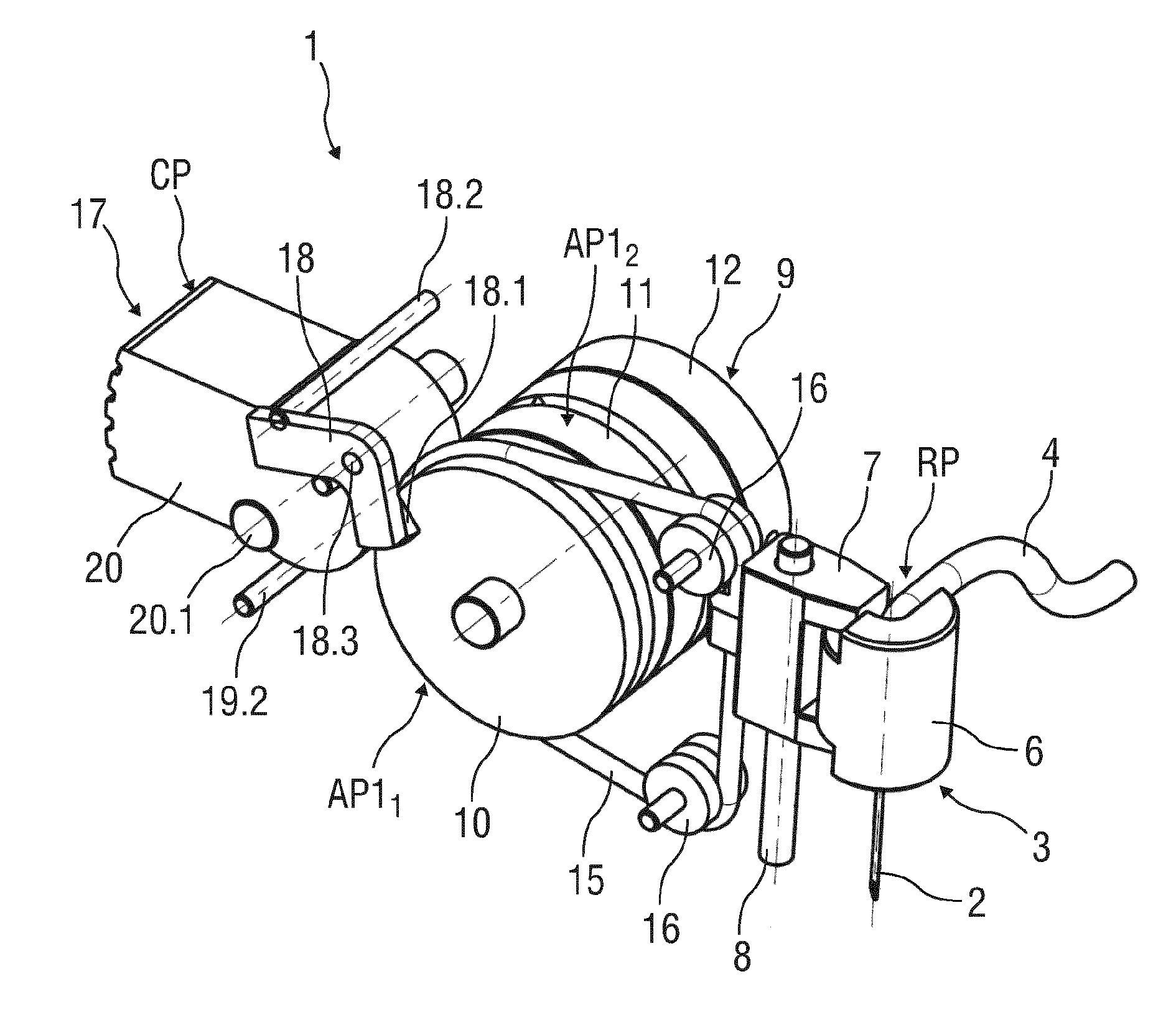
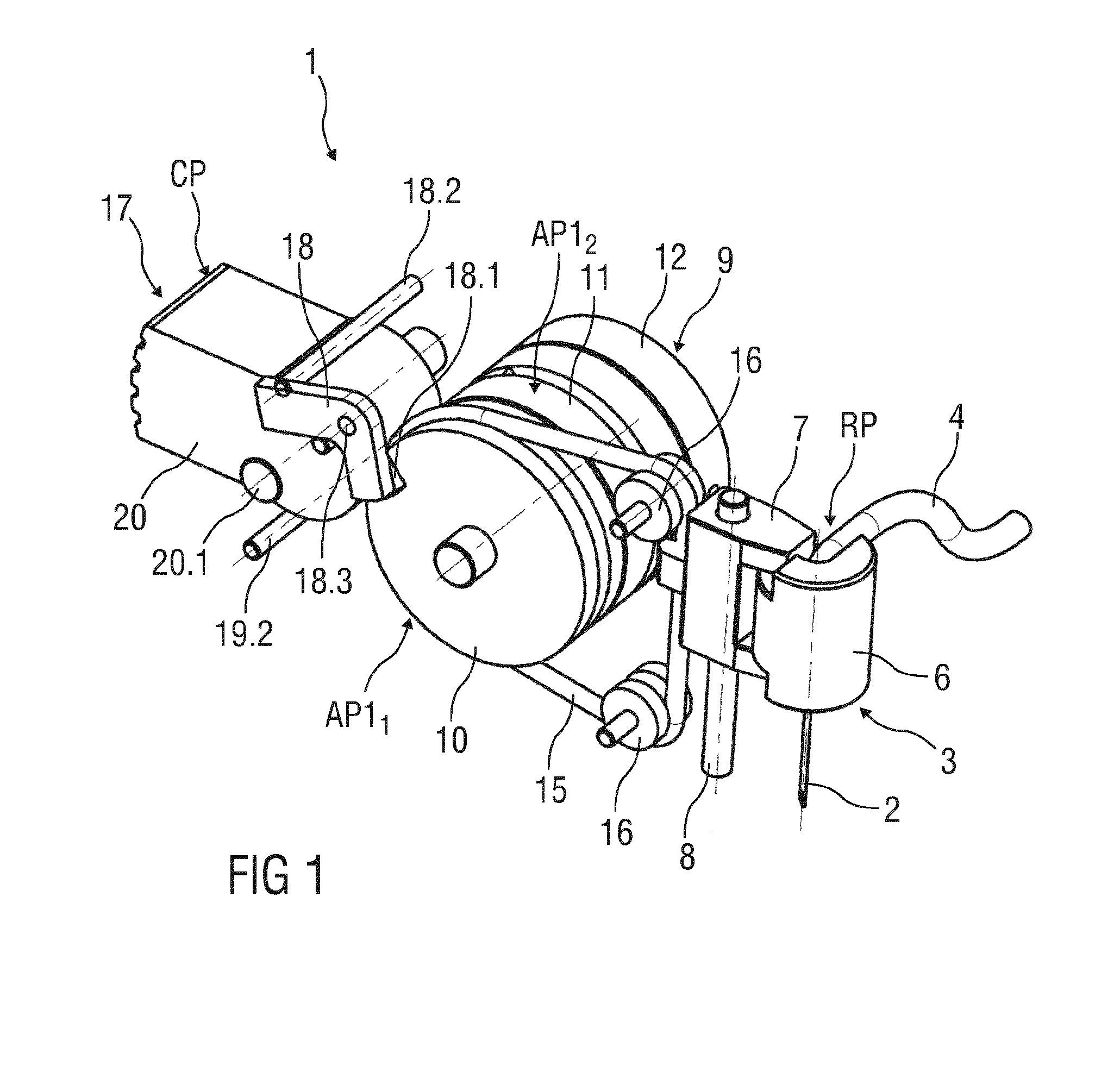
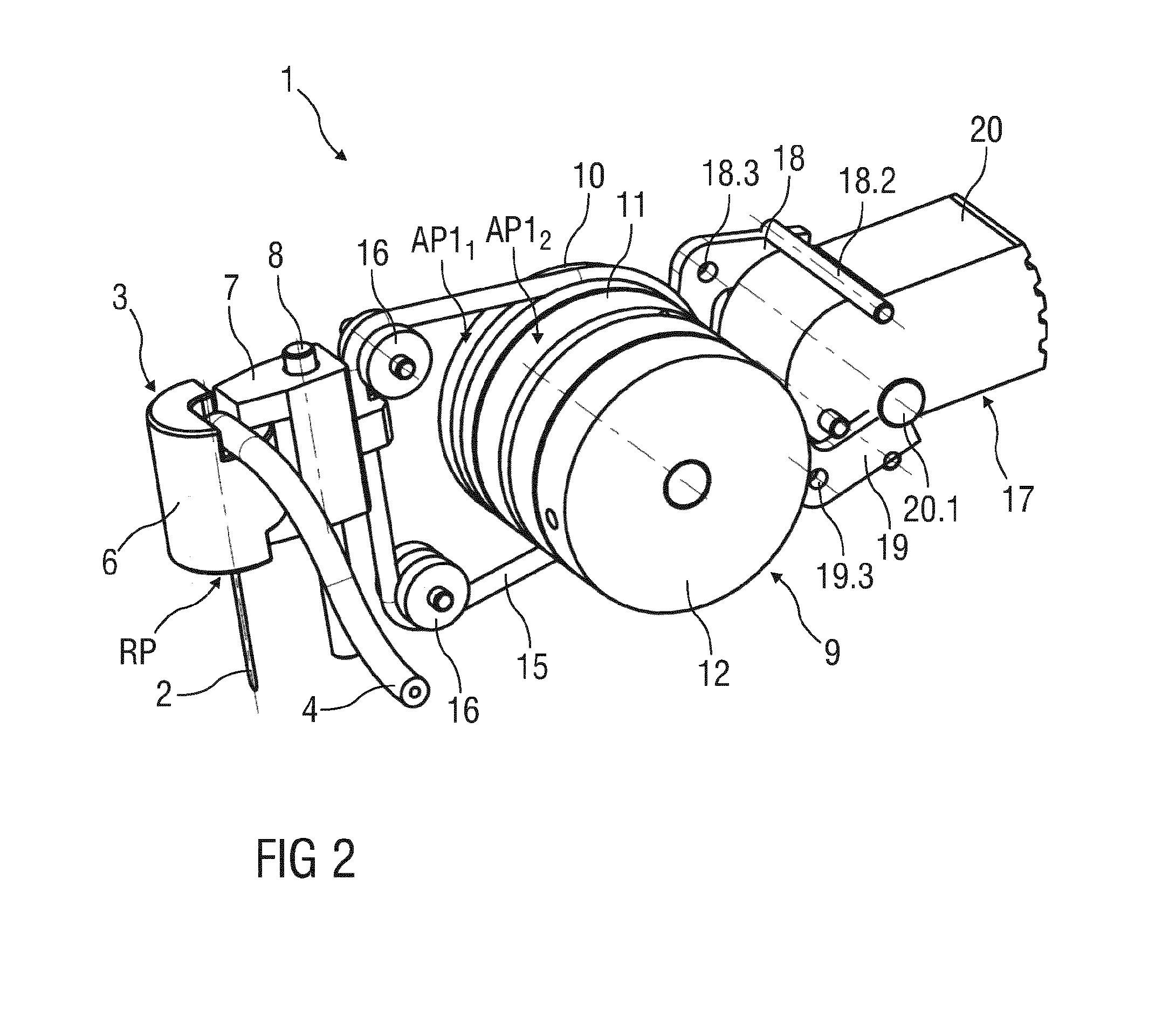
[0045]FIG. 1 is a schematic perspective view of an exemplary embodiment of an insertion arrangement 1 for automatically or semi-automatically inserting an injection needle 2 into an injection site. FIG. 2 is another related perspective view. The arrangement 1 may be applied in medicament pumps, e.g. insulin pumps which may be permanently worn on the body.

[0046]The injection needle 2 is part of a disposable unit 3, further comprising a tube 4 for establishing a fluid communication of the needle 2 with a drug container (not illustrated) and comprising a needle base 6, to which the injection needle 2 may be fixed for mechanically connecting the needle 2 to a drive mechanism 9 of an injection unit (not illustrated). The needle base 6 is inserted in a forked needle retainer 7 which is arranged to be moved up and down in a linear guide 8. This linear movement corresponds to insertion of the needle 2 into the injection site, e.g. subcutaneous body tissue and removal from the injection site...


PUM


Abstract

Disclosed is a needle insertion arrangement (1) with a drive mechanism (9) comprising: a belt (15) frictionally engaging a first roller (10) and a needle retainer (7) with an injection needle (2) fixed to the belt, the first roller being rotatably arranged about an axis (A), a second roller (11) also rotatably arranged about the axis (A), a first spring (13) rotatably biasing the first roller against the second roller, a second spring (14) rotatably biasing the second roller against an arrester (12), the first and the second roller being connected via an internal protrusion (10.2) and arcuate slot (11.2), the two springs (13, 14) biasing the rollers (10, 11) from respective first to respective second angular positions (AP11, AP12, AP21, AP22), and a trigger mechanism (17,20) releasably locking the first and second rollers (10, 11) such that upon pivoting the trigger button (20) in one direction, the first roller drives the belt in one direction to linearly transport the needle retainer towards an extended position, and upon pivoting the trigger button in the other direction, the first roller drives the belt back to retract the needle retainer.

Description

TECHNICAL FIELD[0001]The invention relates to a drive mechanism for a needle insertion arrangement.BACKGROUND OF THE INVENTION[0002]Administering an injection is a process which presents a number of risks and challenges for users and healthcare professionals, both mental and physical. During manual insertion of an injection needle into an injection site, e.g. the skin of a patient, it may be difficult to avoid tilting and bending of the needle and the insertion may be slow thus causing pain.[0003]There remains a need for an improved drive mechanism for a needle insertion arrangement.SUMMARY OF THE INVENTION[0004]It is an object of the present invention to provide an improved drive mechanism for a needle insertion arrangement[0005]The object is achieved by a drive mechanism for a needle insertion arrangement according to claim 1.[0006]Exemplary embodiments of the invention are given in the dependent claims.[0007]According to the invention a drive mechanism for a needle insertion arra...

Claims


Application Information

Patent Timeline
Patent Type & Authority Applications(United States)
IPC IPC(8): A61M5/158
CPCA61M5/158A61M2005/1583A61M2005/1585
Inventor SCHABBACH, MICHAELWERNER, MEINOLFZECKAI, OLAFNZIKE, PHILIPPE
Owner SANOFI AVENTIS DEUT GMBH
Why Eureka
Try Eureka