Engine valve actuation system

a technology of actuators and engine valves, applied in the direction of valve drives, machines/engines, non-mechanical valves, etc., can solve the problems of engine valve collapse and close, engine valves will be opened late, and lose some of the total available valve movement or motion, etc., to avoid impact noise, precise and efficient, and better timing consistency

Active Publication Date: 2016-07-28
NINGBO HOYEA MACHINERY MFG
View PDF10 Cites 10 Cited by
  • Summary
  • Abstract
  • Description
  • Claims
  • Application Information

AI Technical Summary

Benefits of technology

[0020]The present invention provides significant advantages over other lost-motion engine valve actuation systems. By using two control shafts, actuated by electrical motors, to control all trigger valves used in the lost motion system, there will be better timing consistency because the control features, such as flow channel or earn profiles, on these control shafts will be manufactured in the same precise and efficient manner as a regular camshaft has been manufactured over the years. Also, electrical motors are generally more robust than solenoid valves at cold temperatures, and thus the lost-motion system of this invention can activate its throttle-less operation mode in a much broader temperature range and over a wider range of a drive cycle (specially during an engine warm-up), which is consistent with the new industrial trend to replace electrohydraulic variable valve timing systems with electrical variable valve timing systems. The rotary type of trigger valves of this invention operates under more or less steady state rotation mode, avoiding impact noise from reciprocating linear motion of a solenoid valve. A camshaft-like control shaft is generally robust and reliable. Robust and accurate control may also improve overall acceptability of the lost-motion technology such that it will help make possible more advanced combustion modes such as HCCI (homogenous charge compression ignition).

Problems solved by technology

When the solenoid valve is not closed early enough, the engine valve will be opened late and lose some of the total available valve movement or motion.
When the solenoid valve is opened before the end of the cam lobe, a fast bleeding of the fluid from the high pressure chamber will cause the engine valve to collapse and close early, losing some motion or lift.
When the solenoid valve either closes too late or open too early, the engine valve will lose some of the potential motion.
Application vehicles, however, still use the throttle body for air intake control during engine warm up because of above discussed low-temperature operation challenges.

Method used


Image

  • Engine valve actuation system
  • Engine valve actuation system
  • Engine valve actuation system

Examples


Embodiment Construction

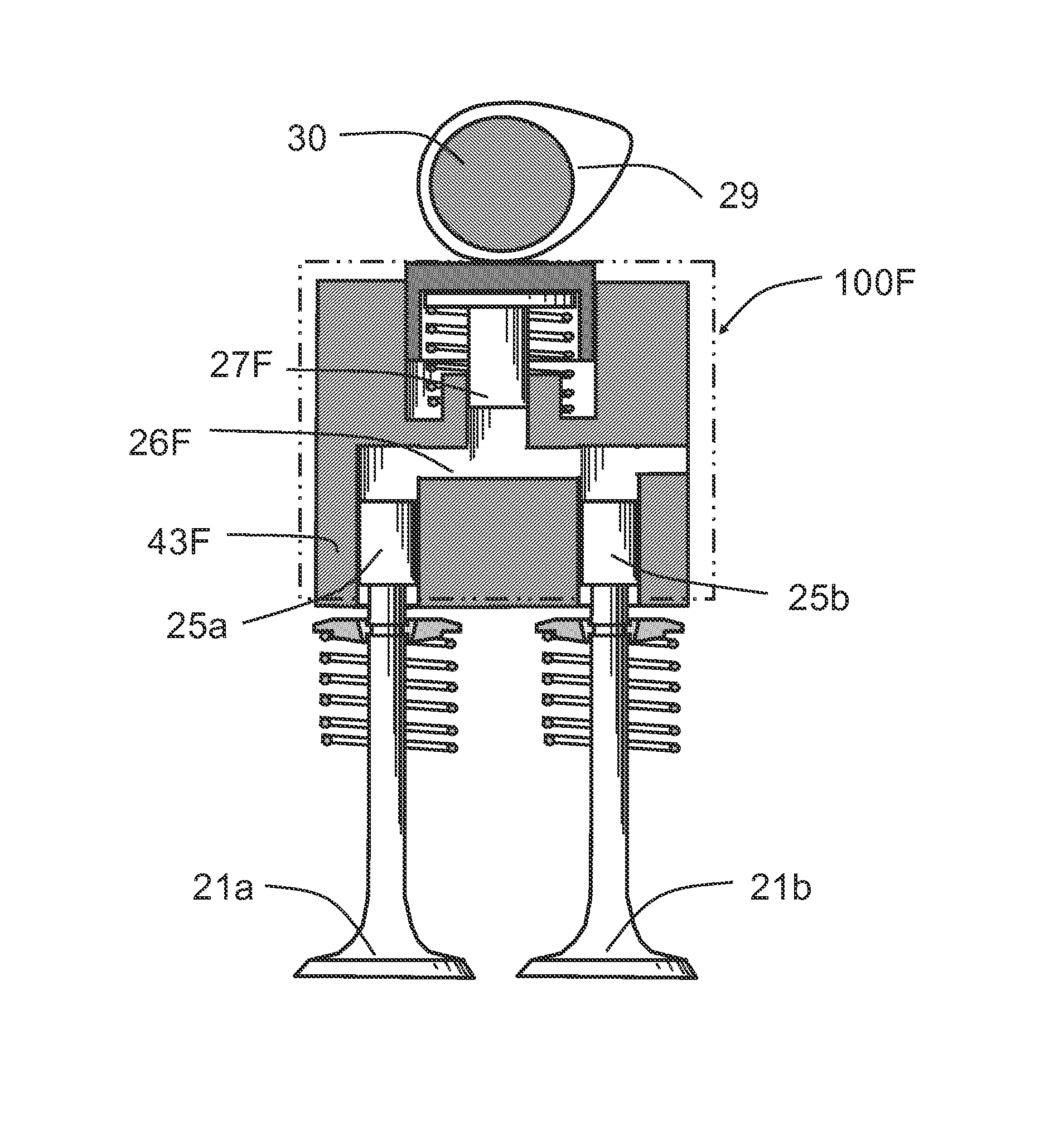
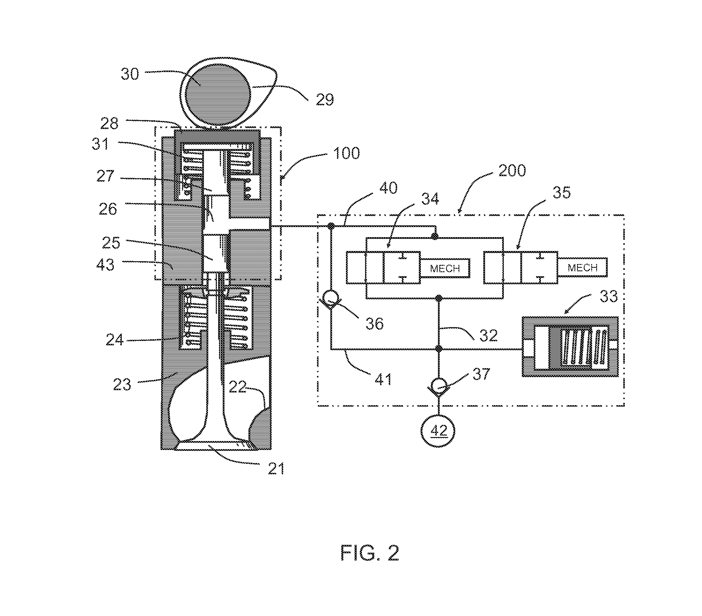
[0039]Please refer to FIG. 2, a preferred embodiment of the present invention FIG. It includes an engine valve 21, which could be an intake valve or an exhaust valve, and a corresponding (intake or exhaust) duct 22 situated in a cylinder head 23 of an internal combustion engine. The engine valve 21 is returned to its closing position (upwardly, with reference to FIG. 2) by a engine-valve return spring 24, while it is driven to open by a slave piston 25 butting against the top of the valve stem. The slave piston 25 is in turn driven, via oil in the high pressure chamber 26 situated in an actuator housing 43, by a master piston 27 under a mechanical tappet 28 operably connected with a cam 29 of a camshaft 30. The mechanical tappet 28 is held against the cam 29, with help from a tappet spring 31.

[0040]The high pressure chamber 26 is connected in serial with a passage two 40, parallelly arranged trigger valve one 34 and trigger valve two 35, and a passage one 32. The passage one 32 is f...


PUM


Abstract

The present disclosure provides an engine valve actuation system comprising: a camshaft, with a plurality of cams: a control shaft one; a control shaft two; and a plurality of valve actuation units, each unit further comprising: (i) at least one set of an engine valve and an engine-valve return spring; (ii) an lost-motion module, further comprising a collapsible high-pressure chamber, and operably converting the profile of the one of the cams and the collapsing motion from the high-pressure chamber to corresponding movement of the at least one engine valve; and (iii) a hydraulic circuit, further comprising: a trigger valve one and a trigger valve two, being controlled respectively by the control shaft one and the control shaft two.

Description

FIELD OF THE INVENTION[0001]This invention relates generally to engine valve actuators and corresponding methods and, in particular, to actuators utilizing lost-motion mechanism with accurate and robust timing control.BACKGROUND OF THE INVENTION[0002]Various systems can be used to actively control the timing and lift of engine valves to achieve improvements in engine performance, fuel economy, emissions and other characteristics. One class of systems, called lost-motion system, has been disclosed in U.S. Pat. Nos. 4,671,221, 5,193,494, 5,839,400, 6,053,136, 6,553,950, 6,918,364, 6,981,476, 7,819,100, 8,578,901, 8,820,276 and 8,776,738. Each of the above lost-motion systems invariably comprises a cam, a master piston, a high pressure chamber, a mechanism to drive an engine valve, an on / off or 2-way solenoid valve as a release valve or trigger valve, an engine valve and an engine-valve return spring. Most of these systems, as disclosed in U.S. Pat. Nos. 4,671,221, 5,193,494, 5,839,400...

Claims


Application Information

Patent Timeline
Patent Type & Authority Applications(United States)
IPC IPC(8): F01L9/02F01L1/18F01L1/46F01L1/14F16K31/122F01L1/047F01L9/10F01L9/14
CPCF01L9/023F16K31/1221F01L1/047F01L1/462F01L1/14F01L1/18F01L13/04F01L1/08F01L1/181F01L1/267F01L2001/0476F01L2800/00F01L2800/01F01L2820/03F02D13/0207F02D13/04F01L2305/00F01L9/14F02M47/027F16K31/122F01L9/10
Inventor LOU, ZHENG
Owner NINGBO HOYEA MACHINERY MFG
Why Eureka
Try Eureka