Exposing storage entity consistency capability status

a technology of consistency and storage entity, applied in the field of exposing storage entity consistency capability status, can solve the problems of physical system crash, data stored in that storage device may be lost, drawback is tempered, etc., and achieve the effect of reducing the amount of data being archived, reducing latency, and reducing the latency when working with such data

Inactive Publication Date: 2016-07-28
MICROSOFT TECH LICENSING LLC
View PDF6 Cites 3 Cited by
  • Summary
  • Abstract
  • Description
  • Claims
  • Application Information

AI Technical Summary

Benefits of technology

[0007]In this manner, a given software module may store data on a most appropriate storage entity. In some cases, a software module may sacrifice some level of consistency capability of the storage entity in exchange for other desired benefits of that storage entity, such as reduced latency. Accordingly, the data stored in that storage device may be lost upon the physical system crashing. However, this drawback is tempered because the data stored therein may be less sensitive to loss because the decision module has chosen to place only such less sensitive data onto such a storage entity. On the other hand, this drawback comes with the technical benefit that latency when working with such data is reduced in the usual circumstance where there is no physical crash of the system.
[0008]In addition, since higher consistency storage entities often provide consistency by archiving, the principles described herein have the potential of reducing the amount of data being archived. After all, data that is less sensitive to consistency may be placed in a storage entity that is not archived at all. This preserves storage, processing, and network bandwidth resources associated with archiving.

Problems solved by technology

Accordingly, the data stored in that storage device may be lost upon the physical system crashing.
However, this drawback is tempered because the data stored therein may be less sensitive to loss because the decision module has chosen to place only such less sensitive data onto such a storage entity.
On the other hand, this drawback comes with the technical benefit that latency when working with such data is reduced in the usual circumstance where there is no physical crash of the system.

Method used


Image

  • Exposing storage entity consistency capability status
  • Exposing storage entity consistency capability status
  • Exposing storage entity consistency capability status

Examples


Embodiment Construction

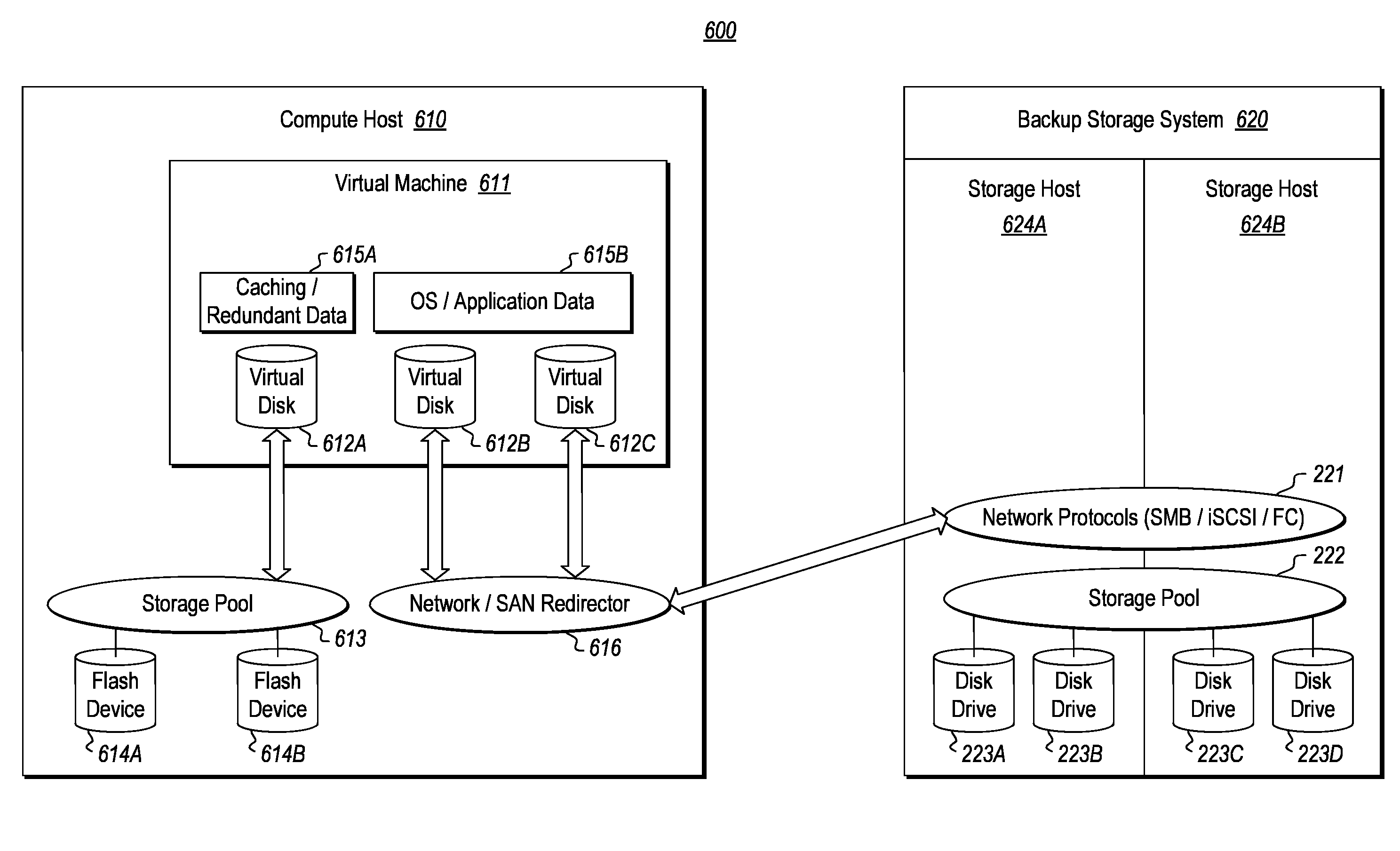
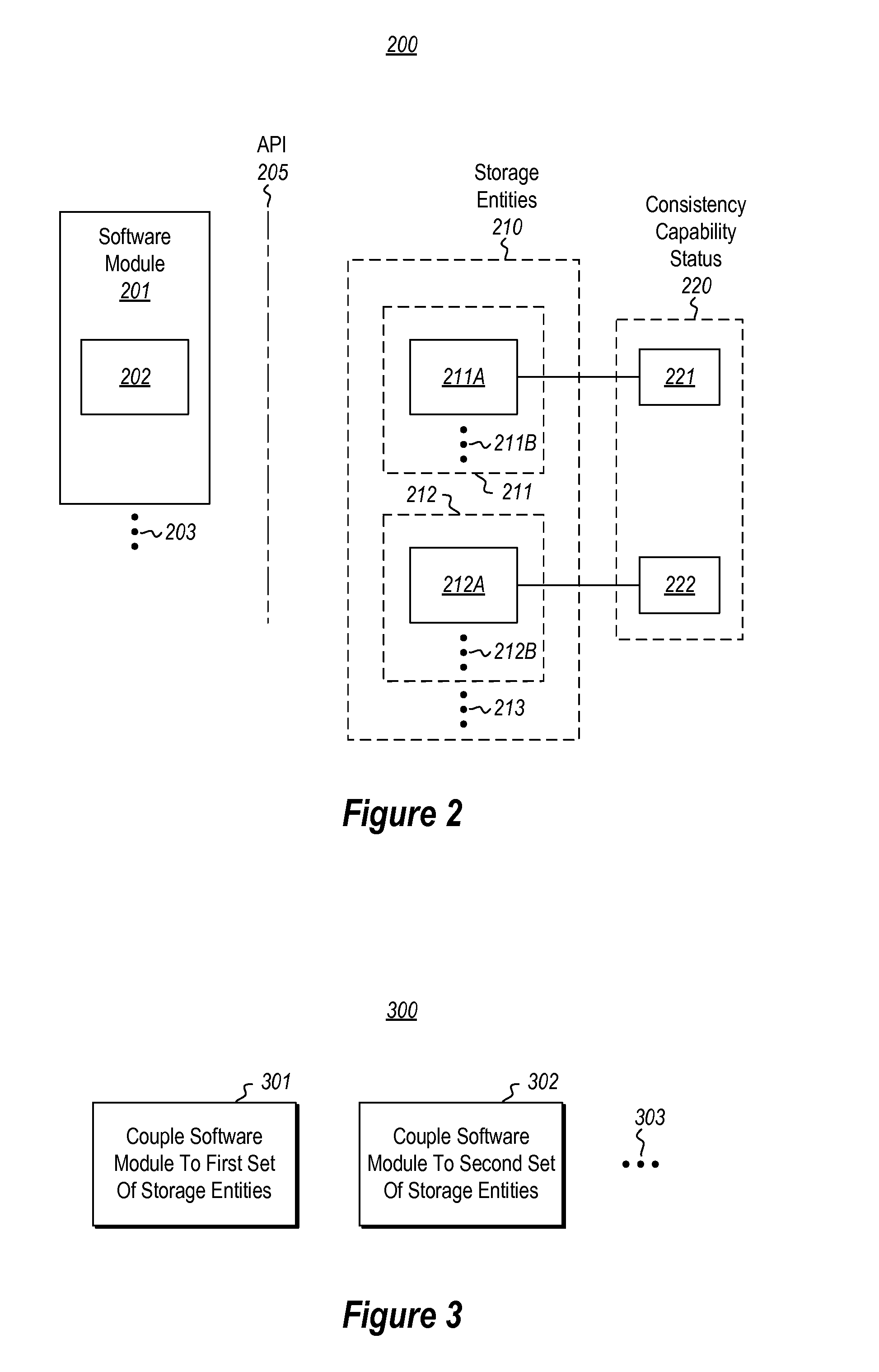
[0017]At least some embodiments described herein relate to the configuration of a software module (e.g., a virtual machine) to interact via an application program interface to storage entities (e.g., a virtual drive) having various consistency capability statuses. The software module is coupled via the application program interface with a first set of one or more storage entities having a first consistency capability status. Furthermore, the software module is configured to discover the first consistency capability status via the application program interface. The software module is further coupled via the application program interface with a second set of one or more storage entities having a second consistency capability status that is different than the first consistency capability status. The software module is further configured to discover the second consistency capability status via the application program interface. The software module thus has available for use storage enti...


PUM


Abstract

A storage entity (e.g., a virtual hard drive) that exposes its technical capabilities including a consistency capability status via an application program interface to a software module (e.g., a virtual machine). The storage entity queries the storage entity through an application program interface to determine technical capabilities of the storage entity. The storage entity responds with a consistency capability status providing a level of consistency that the storage entity is able to provide data stored thereon. The software module may then use this consistency capability status to determine whether to store which data on the storage entity.

Description

BACKGROUND[0001]Computing systems and associated networks have revolutionized the way human beings work, play, and communicate. Computing systems are made functional through their ability to process, retrieve, and store information. Conventionally, processing and storage capabilities have been provided on the local computing system itself. However, more recently, for many computing systems, more and more processing and storage capability has been provided outside of the local computing system, perhaps on another node in a network.[0002]More recently, cloud computing environments have been established in which processing and storage of a local computing system can be performed by one or more remote data centers. Often a single remote computing system (referred to as a “host”) is capable of performing such processing and / or storage for many physical computing systems. One way to do this is by assigning an application called a “virtual machine” to each served computing system.[0003]The...

Claims


Application Information

Patent Timeline
Patent Type & Authority Applications(United States)
IPC IPC(8): G06F9/455G06F17/30G06F9/48
CPCG06F9/45558G06F2009/45583G06F17/30371G06F9/4856G06F9/46G06F11/1448G06F11/20G06F2009/45579G06F2201/815G06F2201/82G06F2201/84G06F9/455G06F11/00
Inventor OSHINS, JACOBLANG, JAMES PATRICK
Owner MICROSOFT TECH LICENSING LLC
Why Eureka
Try Eureka