
Transmission system for machine

a technology of transmission system and transmission system, which is applied in the direction of gearing details, belt/chain/gearing, gear lubrication/cooling, etc., can solve problems such as parasitic losses in the transmission system

Inactive Publication Date: 2016-08-04
CATERPILLAR INC
View PDF1 Cites 0 Cited by
  • Summary
  • Abstract
  • Description
  • Claims
  • Application Information

AI Technical Summary

Benefits of technology

The patent text describes a problem with traditional methods of cooling the contact surface of a stationary clutch in a transmission system. When the clutch is engaged, cooling oil usually does not reach the contact surface, and when it is disengaged, the cooling oil flows through the holes in the clutch hub, causing viscous drag and parasitic losses in the transmission system. The technical effect of this patent is to provide a solution that reduces these losses and improves the efficiency of the cooling process.

Problems solved by technology

However, when the stationary clutch is engaged, i.e., when the clutch hub is stationary, cooling oil usually does not reach the contact surface.
However, due to flow of the cooling oil through the holes in the clutch hub, a viscous drag is generated leading to parasitic losses in the transmission system.

Method used


Image

  • Transmission system for machine
  • Transmission system for machine
  • Transmission system for machine

Examples


Embodiment Construction

[0012]Reference will now be made in detail to specific embodiments or features, examples of which are illustrated in the accompanying drawings. Wherever possible, corresponding or similar reference numbers will be used throughout the drawings to refer to the same or corresponding parts.

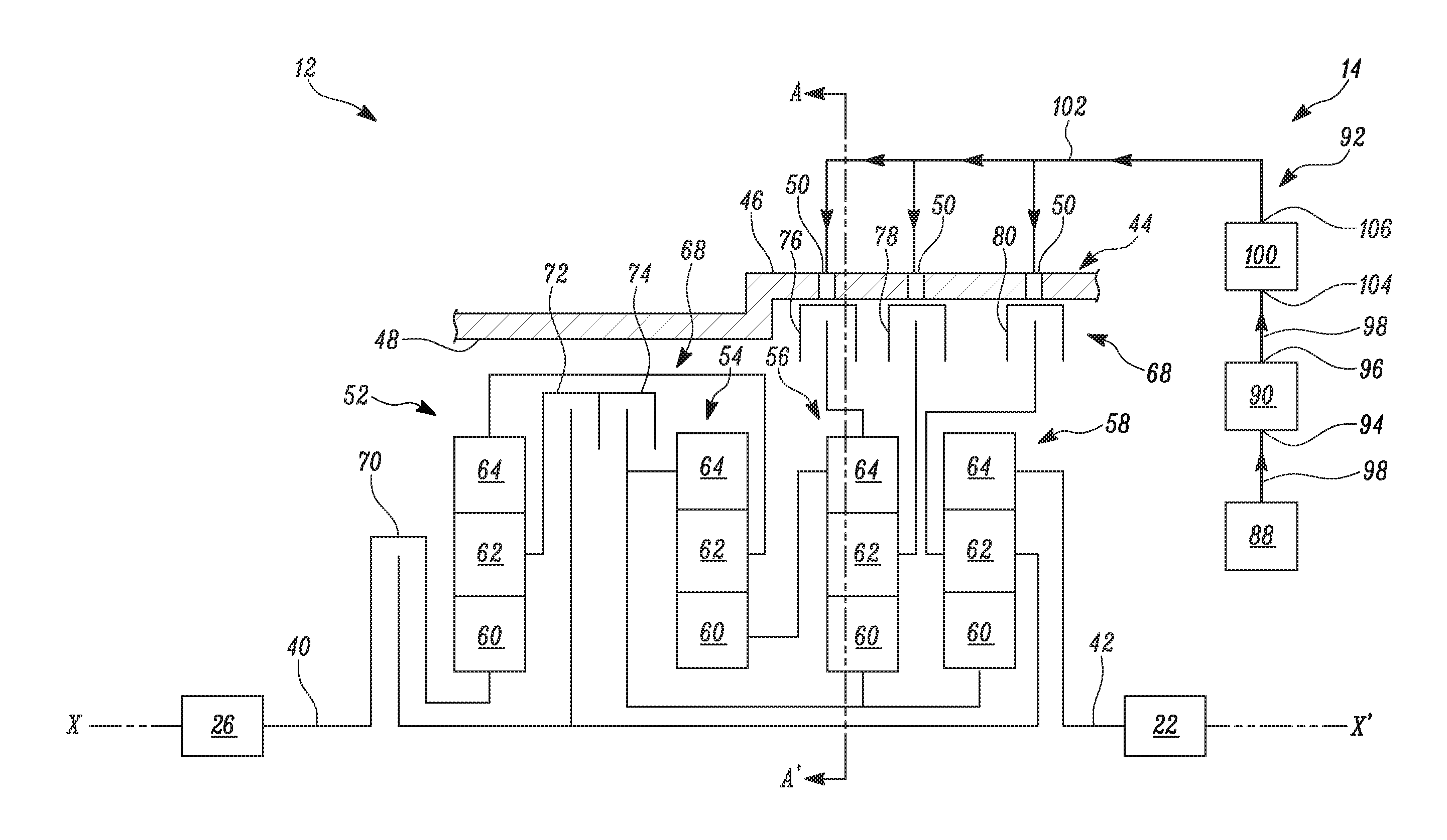
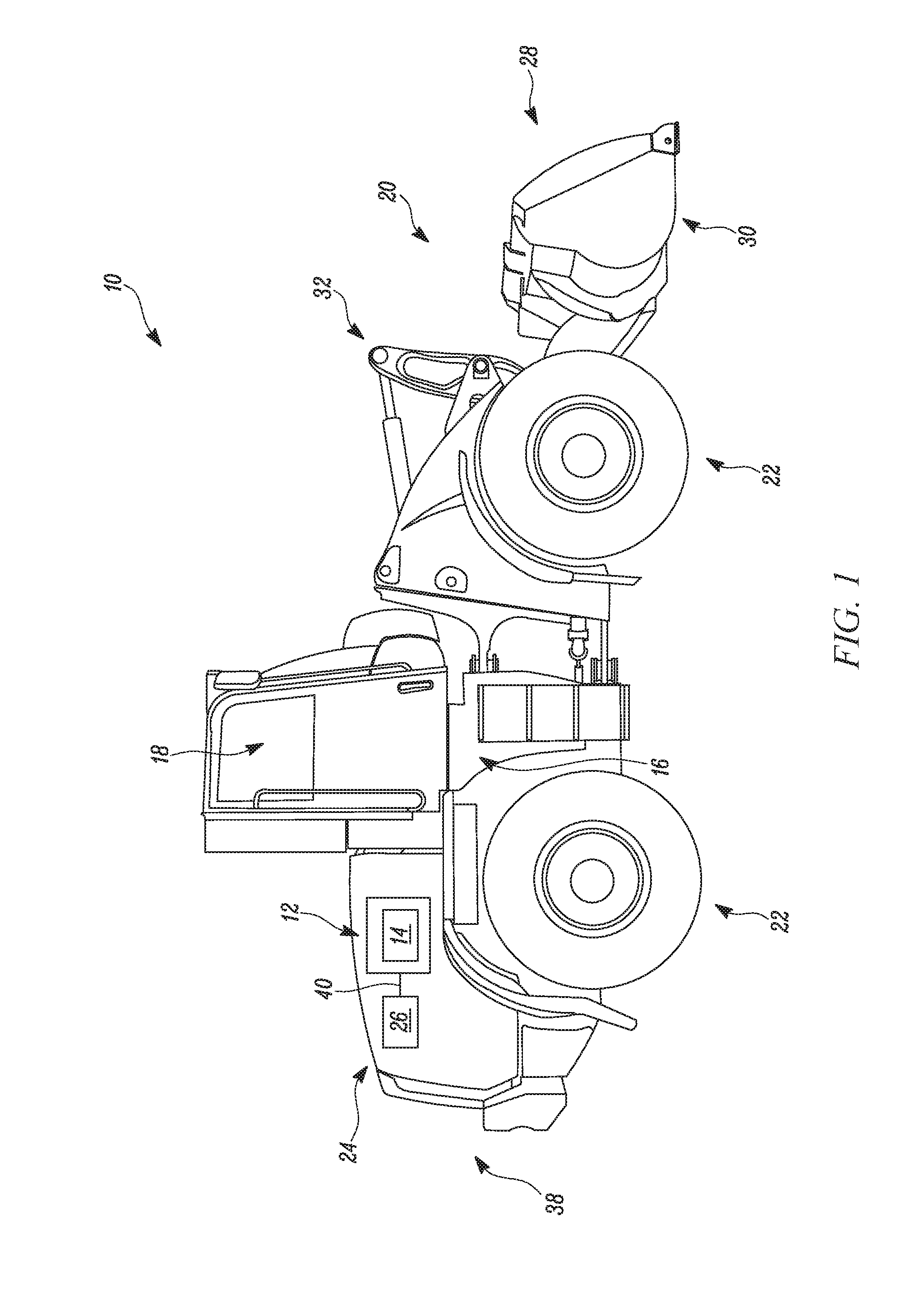
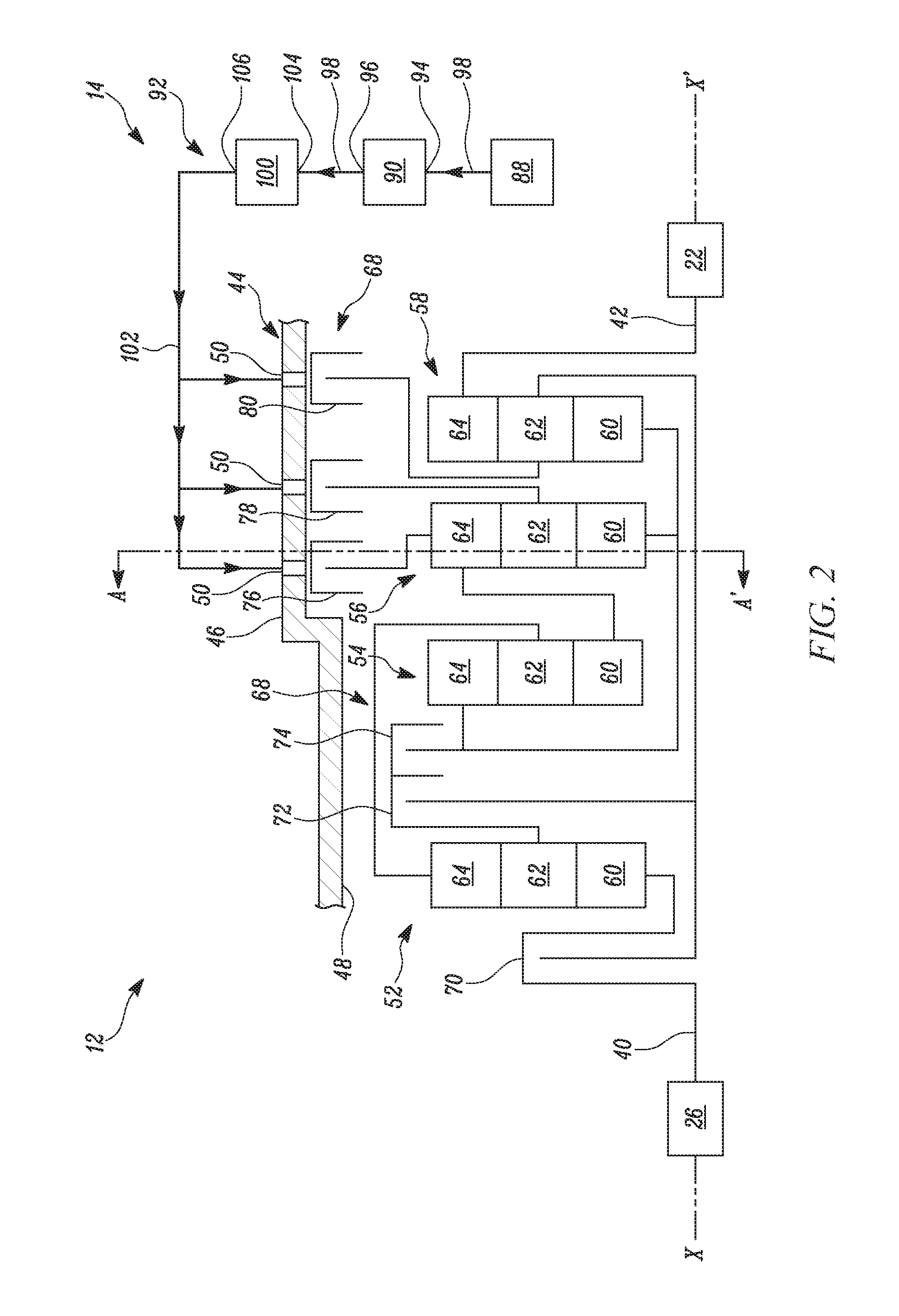
[0013]FIG. 1 is a schematic view of a machine 10 having a transmission system 12 having a clutch cooling system 14, according to one embodiment of the present disclosure. The machine 10 may be an earth moving machine that may include, but is not limited to, a backhoe, an excavator, a tractor, a loader, a motor grader, or any other earth moving machine. In the present example, the machine 10 is embodied as a wheel loader.

[0014]The machine 10 includes a frame 16, an operator cabin 18 for accommodating an operator, an implement system 20 coupled to the frame 16, a pair of ground engaging members 22 for propelling the machine 10, a compartment 24 for accommodating a power source 26, the transmission syste...


PUM


Abstract

A transmission system of a machine is provided. The transmission system includes a housing member having an outer surface and an inner surface. The transmission system includes a clutch assembly disposed within the housing member. The transmission system also includes a clutch cooling system associated with the housing member to selectively supply a fluid to the clutch assembly. The clutch cooling system includes a reservoir for storing the fluid and a pump in fluid communication with the reservoir. The clutch cooling system further includes a fluid supply unit configured to supply the fluid from the reservoir to the clutch assembly. The clutch cooling system supplies the fluid at a plurality of locations around a circumference of the clutch assembly.

Description

TECHNICAL FIELD[0001]The present disclosure relates to transmission systems, and more specifically relates to a cooling system for a transmission system of a machine.BACKGROUND[0002]Stationary clutches are frequently employed in various machines to hold rotating components, such as a sun gear, a ring gear, or a planet carrier of a transmission system. The stationary clutches control torque or speed ratios received from the rotating components During operation of the stationary clutches, i.e., engagement and disengagement of the stationary clutches, heat is generated due to friction between contact surfaces.[0003]Conventionally, in order to remove the heat generated, cooling oil is supplied to a contact surface of the stationary clutch through a number of holes. The holes are typically formed in a clutch hub. However, when the stationary clutch is engaged, i.e., when the clutch hub is stationary, cooling oil usually does not reach the contact surface. When the stationary clutch is di...

Claims


Application Information

Patent Timeline
Patent Type & Authority Applications(United States)
IPC IPC(8): F16H57/04
CPCF16H57/0484F16H57/0473
Inventor MEYER, KEVIN G.RICE, JAMES S.
Owner CATERPILLAR INC
Learn More