
Stator Cooling Arrangement

Pending Publication Date: 2022-11-10
ABB (SCHWEIZ) AG
View PDF3 Cites 0 Cited by
  • Summary
  • Abstract
  • Description
  • Claims
  • Application Information

AI Technical Summary

Benefits of technology

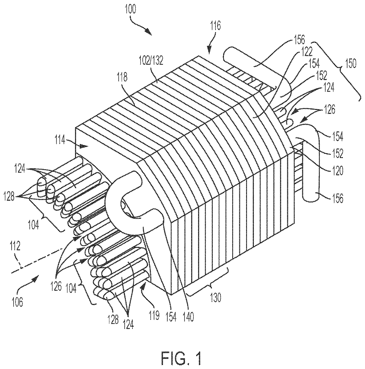
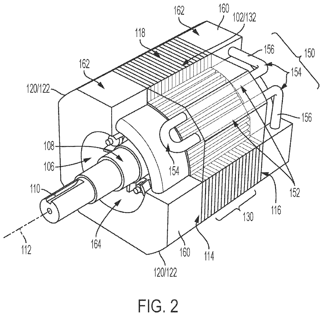
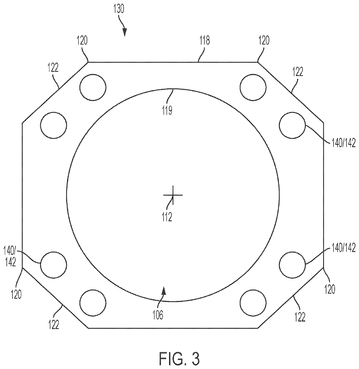
The patent describes a way to cool a rotating electric machine using a fluid coolant. The machine has a stator core with windings and cooling channels. The cooling channels are made up of linear tubes and elbow tubes that are coupled together to transfer heat from the stator windings. The end turns of the windings make contact with the elbow tubes outside of the stator core. To improve the transfer of heat, the end turns and the elbow tubes are encased in a stator end casting made from thermally conductive and insulating material. The invention helps to increase efficiency and reliability of the rotating electric machine.

Problems solved by technology

However, to cool machines intended for larger applications, for example, on the order several hundred watts, air cooling may be insufficient or may require the machine include a significant amount of exposed surfaces that the power density is significantly reduced.
Because of the laminated construction, though, the cooling liquid directed through the channels may leak through adjacent laminations.

Method used


Image

  • Stator Cooling Arrangement
  • Stator Cooling Arrangement
  • Stator Cooling Arrangement

Examples


Embodiment Construction

[0012]Now referring to the drawings where, whenever possible, like reference numbers will refer to like elements, there is illustrated in FIGS. 1 and 2 a stator assembly 100 for a rotating electrical machine such as, for example, an electric motor that converts electrical energy to rotational motion that is output via a rotating motor shaft that is applied to a load. Aspects of the disclosure, however, will be applicable to other types of rotating electrical machines such as generators and to non-rotating machines such as linear actuators. Additionally, the stator assembly 100 may be particularly designed for alternative current motors operating on single phase or polyphase electrical current and intended to produce kilowatt levels of power and intended for industrial applications. However, aspects of the disclosure are applicable to motors of various sizes and intended applications and having various different electrical characteristics.

[0013]The stator assembly 100 can include a s...


PUM


Abstract

A stator assembly for a rotating electrical machine is operatively associated with an internal cooling circuit including a plurality of cooling channels disposed through a stator core. To directed a liquid coolant medium through the stator core without leakage, the internal cooling circuit is formed from a plurality of cooling tubes including linear tubes and elbow tubes. Linear tubes are disposed in the cooling channels and can be expanded with a hydraulic expansion tool to frictionally fit the linear tube therein. The elbow tubes can fluidly couple two or more linear tubes and are disposed proximately beyond the first and second axial end faces of the stator core. To encapsulate the elbow tubes, first and second stator end castings of thermally conductive, electrically isolating material can be cast adjacent the first and second axial end faces.

Description

BACKGROUND[0001]Rotating electrical machines such as motors and generators typically include a rotor accommodated within and rotatable with respect to fixed stator. The stator may include a stator core defining a rotor bore for accommodating the rotor and may include a plurality of stator windings in the form of wound conductive wires. The rotor, stator core, and stator windings are made from electromagnetic materials to electromagnetically interact with each other. In the case of a motor, an electric current applied to the stator windings causes the rotor to rotate and in the case of a generator, rotational motion applied to the rotor generates an electrical current in the stator windings.[0002]During operation, the components of the rotating electrical machine generate heat due to, for example, electrical resistance of the stator windings, eddy currents induced by the electromagnetic interaction, bearing friction, and the like. To remove the generated heat, the rotating electrical...

Claims


Application Information

Patent Timeline
Patent Type & Authority Applications(United States)
IPC IPC(8): H02K1/20H02K9/19H02K15/02
CPCH02K1/20H02K9/19H02K15/02H02K2213/03H02K9/197H02K15/024
Inventor XING, WEISHRESTHA, GHANSHYAM
Owner ABB (SCHWEIZ) AG
Learn More