Heat dissipation device with heat pipes

a heat dissipation device and heat pipe technology, which is applied in the direction of semiconductor/solid-state device details, lighting and heating apparatus, instruments, etc., can solve the problems of increasing complexity and sophistication of the electronic circuit layout of the new generation central processing unit (cpu), generating new problems in use, and increasing the complexity of the electronic circuit layout of the old one. achieve the effect of reducing the volume of the device, increasing the heat dissipation efficiency, and facilitating transmission

Active Publication Date: 2005-09-15
QUANTA COMPUTER INC
View PDF3 Cites 2 Cited by
  • Summary
  • Abstract
  • Description
  • Claims
  • Application Information

AI Technical Summary

Benefits of technology

[0012] The L-shaped heat pipe increases a contact area for transmitting heat between the base and the L-shaped heat pipe so that the heat generated by the heat source can be easily transmitted to the heat fins via the L-shaped heat pipe and removed therefrom. Hence, the heat dissipation device according to the present invention can effectively increase heat dissipation efficiency and the volume thereof is reduced to save a required occupation space in an electrical device.

Problems solved by technology

With progress in semiconductor manufacturing processes and semiconductor functions, electronic circuit layout of semiconductors has become increasingly complicated and sophisticated.
For example, an electronic circuit layout of a new generation central processing unit (CPU) is more complicated than that of an old one because the new generation CPU has to provide more powerful functions for users and application software.
The new generation CPU provides powerful functionality and performance but also generates new problems in use.
One serious problem is that the new generation CPU, with its more complicated circuitry, has higher power consumption and thus has a higher working temperature.
The higher working temperature can cause instability in an operating system of the computer.
On the contrary, if the computer working temperature is too high, the performance and stability will decrease and the operating system may even crash in some extreme situations.
Conventionally, a heat dissipation device is mounted on a new generation CPU having high power consumption to exhaust directly the heat generated by the CPU.
However, the heat dissipation devices with high heat dissipating efficiency usually have large size, which is not suitable for new generation computers, since they are constantly decreasing in volume.

Method used


Image

  • Heat dissipation device with heat pipes
  • Heat dissipation device with heat pipes
  • Heat dissipation device with heat pipes

Examples


Embodiment Construction

[0018] The following description is of the best presently contemplated mode of carrying out the present invention. This description is not to be taken in a limiting sense but is made merely for the purpose of describing the general principles of the invention. The scope of the invention should be determined by referencing the appended claims.

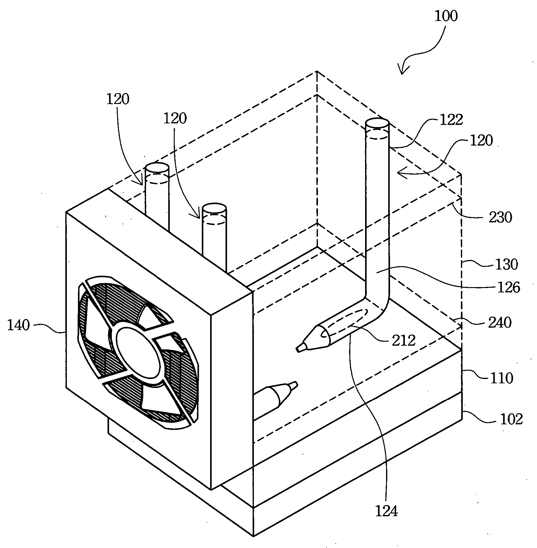
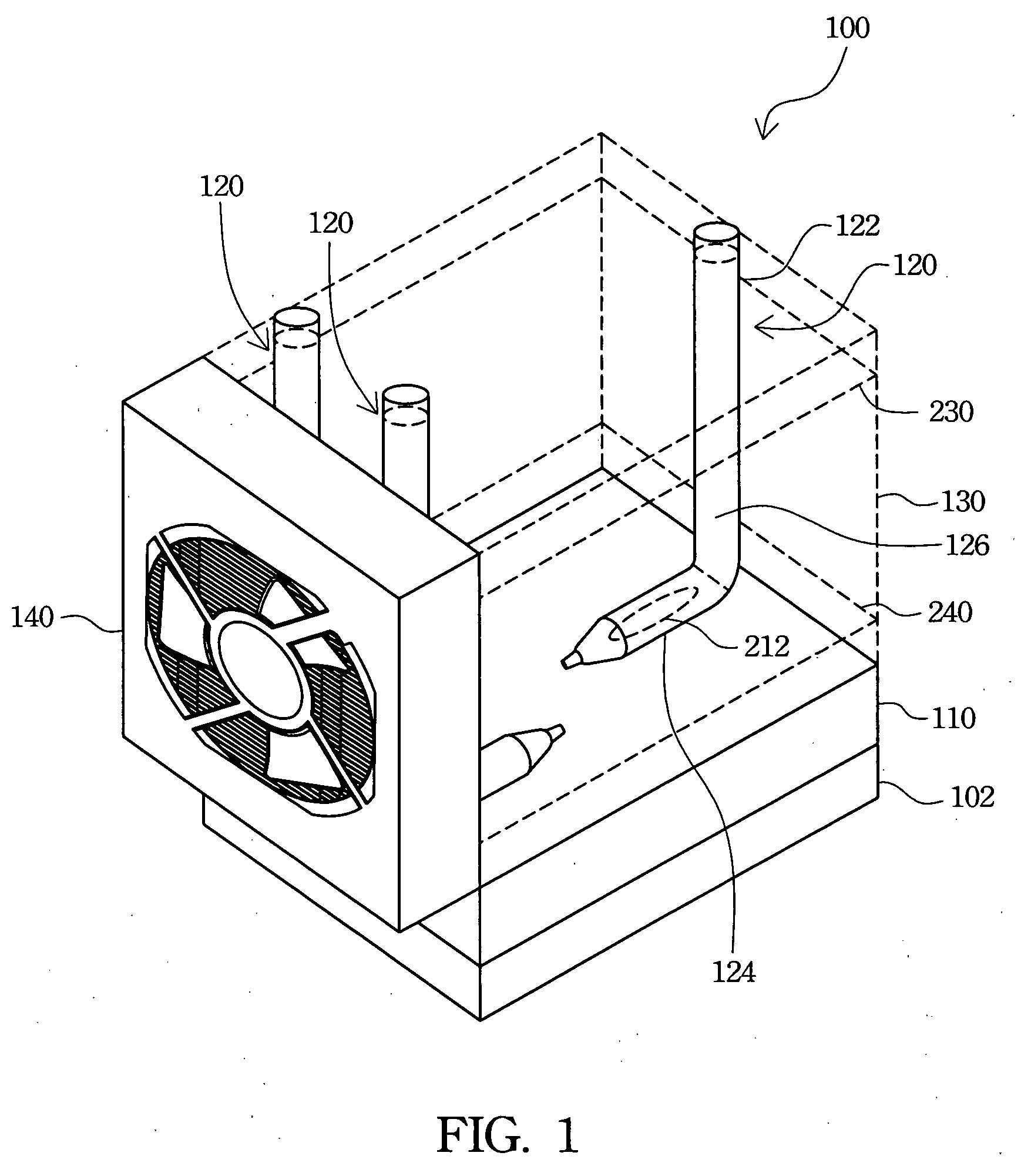
[0019]FIG. 1 is a schematic view of a preferred embodiment of a heat dissipation device with L-shaped heat pipes according to the present invention. The heat dissipation device 100 has a base 110, L-shaped heat pipes 120 and a plurality of heat fins 130. The L-shaped heat pipes 120 and the heat fins 130 are configured on the base 110, and the heat fins 130 are coupled to the L-shaped heat pipes 120. A under surface of the base 110 couples to a central processing unit (CPU) 102 or any other heat source to absorb heat generated therefrom and transmit the heat to the heat fins 130 disposed parallel to the base 110 via the L-shaped heat pipe 120. T...


PUM


Abstract

A heat dissipation device with heat pipes is described. The heat dissipation device has at least one L-shaped heat pipe, a plurality of heat fins, and a heat sink base. One end of the L-shaped heat pipe is coupled to one heat pipe fixing trench of the heat sink base so as to increase a contact area for transmitting heat and therefore improve a heat dissipation efficiency thereof. The heat fins includes at least one upper heat fin and at least one lower heat fin to couple to the L-shaped heat pipe via a round opening and a long opening respectively. The heat dissipation device therefore reduces a volume thereof and save an occupation space in an electrical device.

Description

RELATED APPLICATIONS [0001] The present application is based on, and claims priority from, Taiwan Application Serial Number 93106395, filed on Mar. 10, 2004, the disclosure of which is hereby incorporated by reference herein in its entirety. FIELD OF THE INVENTION [0002] The present invention relates to a heat dissipation device, and more particularly, to a heat dissipation device with L-shaped heat pipes. BACKGROUND OF THE INVENTION [0003] Information technology and the computer industry are highly developed now. Because computers have powerful calculation capability and can deal with a great amount of digital data, computers are popularly used in myriad applications. With progress in semiconductor manufacturing processes and semiconductor functions, electronic circuit layout of semiconductors has become increasingly complicated and sophisticated. [0004] For example, an electronic circuit layout of a new generation central processing unit (CPU) is more complicated than that of an o...

Claims


Application Information

Patent Timeline
Patent Type & Authority Applications(United States)
IPC IPC(8): H05K7/20
CPCG06F1/20H01L23/427F28D15/0275H01L2924/0002H01L2924/00
Inventor CHIN, HSIANG-JUNGCHAN, HUNG-CHOUHUANG, WEN-LIANGCHEN, CHAO-JUNG
Owner QUANTA COMPUTER INC
Why Eureka
Try Eureka