Non-isotropic acoustic cable

Active Publication Date: 2016-08-04
SILIXA
View PDF26 Cites 22 Cited by
  • Summary
  • Abstract
  • Description
  • Claims
  • Application Information

AI Technical Summary

Benefits of technology

The patent describes using a layer of air or other material with low acoustic coupling to reduce the transmission of acoustic energy in a cable. This helps to create an acoustic insulating layer that effectively absorbs acoustic energy and reduces its transmission. Additionally, the patent suggests adding segments of acoustically reactive material to enhance the cable's ability to detect and respond to acoustic signals in specific directions. Overall, this technology improves the cable's ability to detect and respond to acoustic signals while also reducing unwanted noise.

Problems solved by technology

In some deployments, however, it is not possible to secure the cable with clamps, and instead the cable may be inserted in a concrete trench or the like running parallel to a pipe, well, or any other structure being monitored.
As a consequence, due to the sensing resolution of the fibre being less than the actual resolution of the points at which acoustic energy is being sensed, aliasing effects can occur in the signal, due to undersampling.
Another problem faced when using fibre optic cables in distributed acoustic sensing is that acoustic signals incoming from one direction may overcome acoustic signals incoming from another direction, making it difficult for the fibre optic cable to detect the latter.
This may prove problematic for certain applications of distributed acoustic sensing.
However, in security surveillance, it is the incoming acoustic signals caused by disturbances in regions surrounding the asset that are of interest.

Method used


Image

  • Non-isotropic acoustic cable
  • Non-isotropic acoustic cable
  • Non-isotropic acoustic cable

Examples


Embodiment Construction

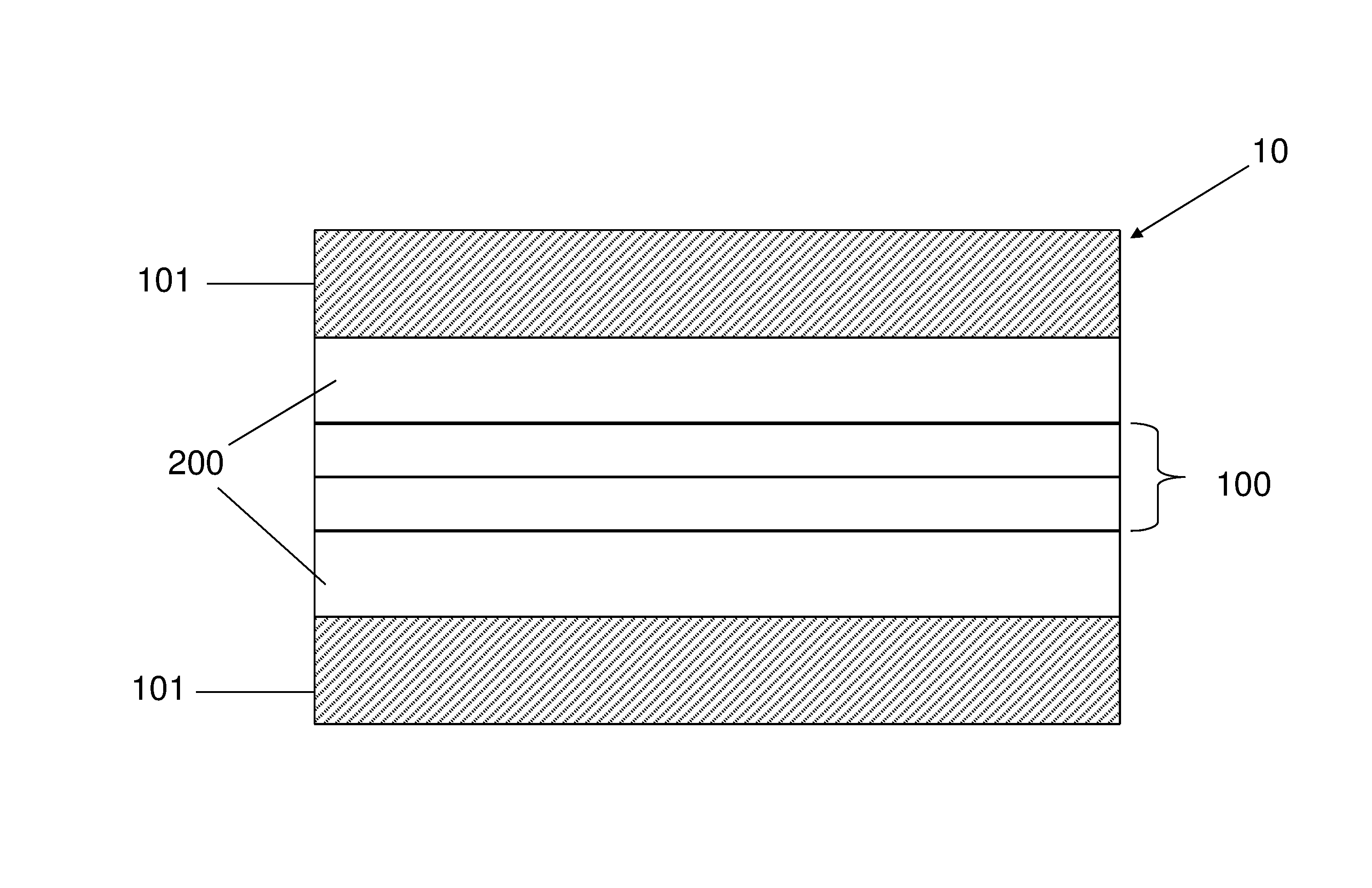
[0066]In a particular embodiment of the invention, described here in order to provide an example of a preferred implementation of the present invention, a distributed acoustic sensor is provided along a fibre optic cable, which emulates having a plurality of discrete sensing points. In order to emulate the discrete points of acoustic coupling, the acoustic coupling between the outer layer and the at least one optical fibre arrangement is adapted as will be described.

[0067]With reference to FIG. 3, there is provided a length of fibre optic cable 10 comprising at least one optical fibre arrangement 100 surrounded concentrically by an outer layer 101, wherein a gap 200 is provided between the at least one optical fibre arrangement 100 and the outer layer 101. The gap 200 comprises at least one acoustic insulating material, typically air, which exhibits low acoustic coupling. The air layer 200 acts as a sound insulating layer between the outer layer 101 and the at least one optical fibr...


PUM


Abstract

Embodiments of the present invention address aliasing problems by providing a plurality of discrete acoustic sensors along a cable whereby acoustic signals may be measured in situations where the fibre optic cable has not been secured to a structure or area by a series of clamps, as described in the prior art. Acoustic sampling points are achieved by selectively enhancing the acoustic coupling between the outer layer and the at least one optical fibre arrangement, such that acoustic energy may be transmitted selectively from the outer layer to the at least one optical fibre arrangement. The resulting regions of acoustic coupling along the cable allow the optical fibre to detect acoustic signals. Regions between the outer layer and the at least one optical fibre arrangement that contain material which is acoustically insulating further this enhancement since acoustic waves are unable to travel through such mediums, or at least travel through such mediums at a reduced rate.

Description

TECHNICAL FIELD[0001]The present invention relates to a fibre optic cable, and in some embodiments provides a fibre optic cable which has an acoustic sensitivity that is non-isotropic. In other embodiments there is provided a fibre optic cable which comprises an array of discrete acoustic coupling regions.BACKGROUND TO THE INVENTION AND PRIOR ART[0002]To detect an acoustic signal, distributed acoustic sensing is commonly and effectively used. This method employs fibre optic cables to provide distributed acoustic sensing whereby the fibre optic cable acts as a string of discrete acoustic sensors, and an optoelectronic device measures and processes the returning signal. The operations of such a device is described next.[0003]A pulse of light is sent into the optical fibre, and a small amount of light is naturally back scattered, along the length of the fibre by Rayleigh, Brilliouin and Raman scattering mechanisms. The scattered light is captured by the fibre and carried back towards t...

Claims


Application Information

Patent Timeline
IPC IPC(8): G01H9/00G02B6/44G01L1/24
CPCG01H9/004G01L1/242G01M7/00G02B6/4415G02B6/4405
Inventor FARHADIROUSHAN, MAHMOUDFINFER, DANIELSTRUSEVICH, DMITRYSHATALIN, SERGEYPARKER, TOM
Owner SILIXA
Why Eureka
Try Eureka