MRAM having spin hall effect writing and method of making the same

a technology of magneticrandom access and memory, applied in the field of three-terminal spintransfertorque magneticrandomaccess memory (mram) elements, can solve problems such as element unrecordable, information readout errors increase, value change, etc., and achieve the effect of quick switching or revers

Active Publication Date: 2016-08-04
GUO YIMIN
View PDF5 Cites 26 Cited by
  • Summary
  • Abstract
  • Description
  • Claims
  • Application Information

AI Technical Summary

Benefits of technology

[0013]An exemplary embodiment includes a structure of a three terminal SHE spin-transfer-torque magnetoresistive memory including a bit line positioned adjacent to selected ones of the plurality of magnetoresistive memory elements to supply a reading current across the magnetoresistive element stack and two highly conductive bottom electrodes overlaid and electrically contacting on top of a SHE-metal layer in the outside of an MTJ region and to supply a bi-directional spin Hall effect recording current, and accordingly to switch the magnetization of the recording layer. Thus magnetization of a recording layer can be readily switched or reversed to the direction in accordance with a direction of a current along the SHE-metal layer by applying a low write current.

Problems solved by technology

More, even when the tunnel barrier does not immediately break down, if recording operations are repeated, the element may still become nonfunctional such that the resistance value changes (decreases) and information readout errors increase, making the element un-recordable.
Furthermore, recording is not performed unless a sufficient voltage or sufficient spin current is applied.
Accordingly, problems with insufficient recording arise before possible tunnel barrier breaks down.
Since the thin GSHE-metal layer in outside regions is connected with MTJs in series as electrodes having a large resistance, the effective magnetoresistive ratio is reduced and degrades output signal and reading performance.

Method used


Image

  • MRAM having spin hall effect writing and method of making the same
  • MRAM having spin hall effect writing and method of making the same
  • MRAM having spin hall effect writing and method of making the same

Examples


Embodiment Construction

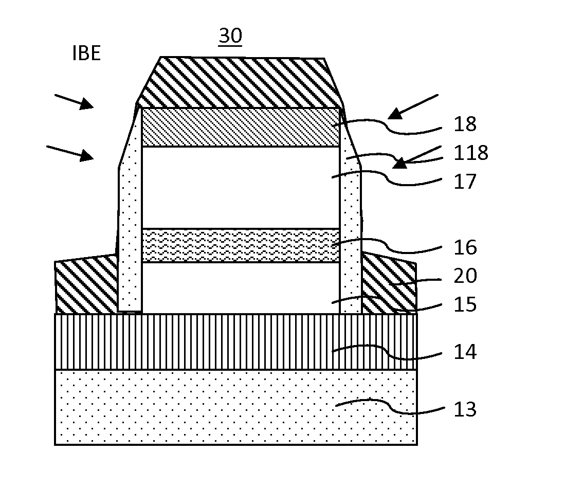
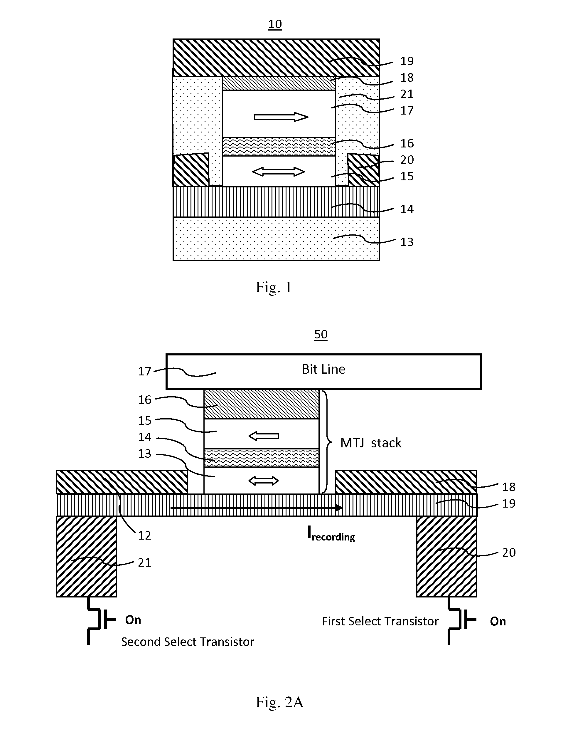
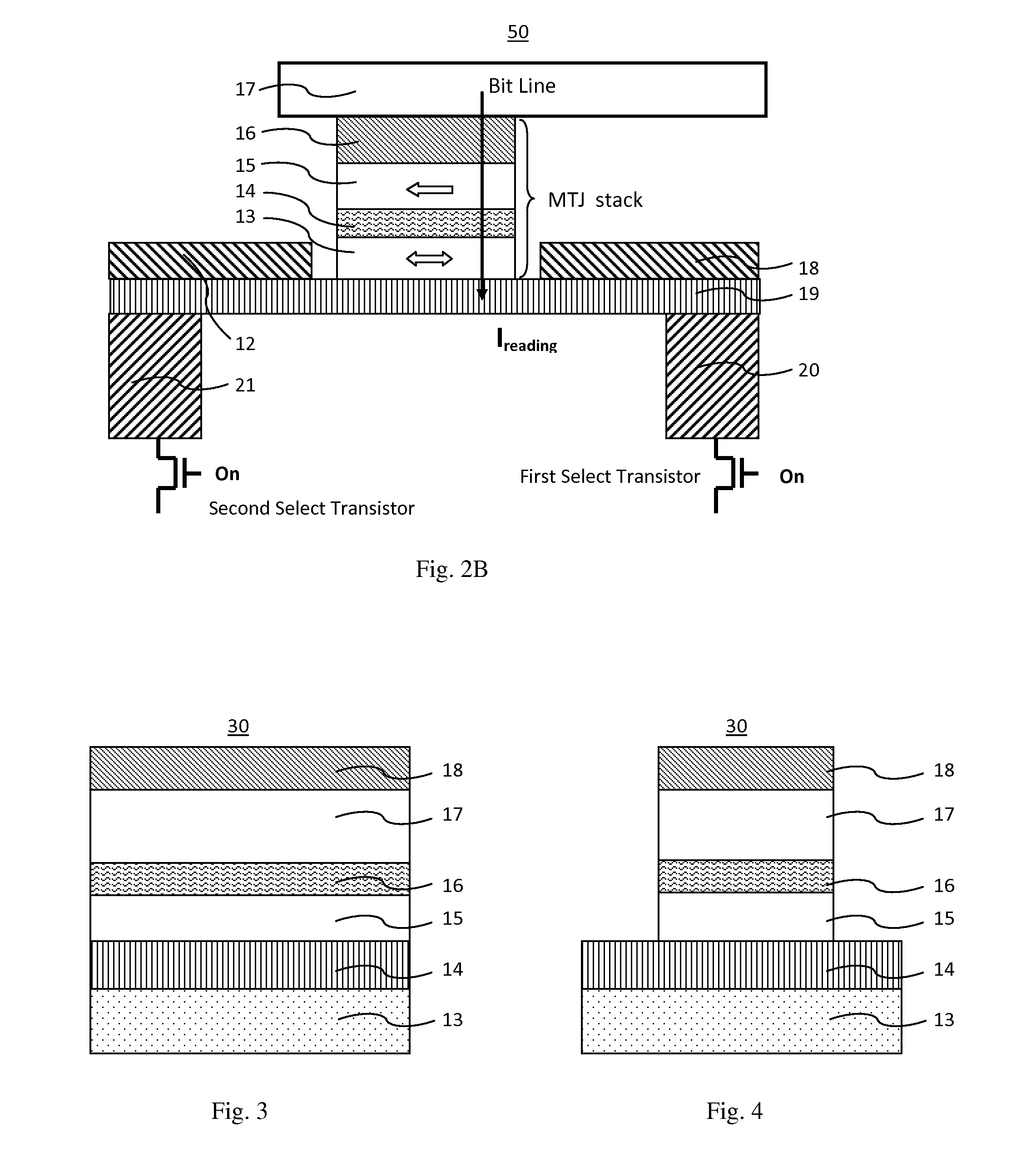
[0029]In general, according to each embodiment, there is provided a three terminal magnetoresistive memory cell comprising:

[0030]a SHE metal layer provided on a surface of a substrate;

[0031]a recording layer provided on the top surface of the SHE layer having magnetic anisotropy in a film plane and having a variable magnetization direction;

[0032]a tunnel barrier layer provided on the top surface of the recording layer;

[0033]a reference layer provided on the top surface of the tunnel barrier layer having magnetic anisotropy in a film plane and having an invariable magnetization direction;

[0034]a cap layer provided on the top surface of the reference layer as an upper electric electrode;

[0035]a first bottom electrode provided on a first side of the SHE metal layer and electrically connected to the SHE metal layer;

[0036]a second bottom electrode provided on a second side of the SHE metal layer and electrically connected to the SHE metal layer;

[0037]a bit line provided on the top surfac...


PUM


Abstract

A spin-transfer-torque magnetoresistive memory comprises apparatus and method of manufacturing a three terminal magnetoresistive memory element having highly conductive bottom electrodes overlaid on top of a SHE-metal layer in the regions outside of an MTJ stack. The memory cell comprises a bit line positioned adjacent to selected ones of the plurality of magnetoresistive memory elements to supply a reading current across the magnetoresistive element stack and two highly conductive bottom electrodes overlaid and electrically contacting on top of a SHE-metal layer in the outside of an MTJ region and to supply a bi-directional spin Hall effect recording current, and accordingly to switch the magnetization of the recording layer. Thus magnetization of a recording layer can be readily switched or reversed to the direction in accordance with a direction of a current along the SHE-metal layer by applying a low write current.

Description

RELATED APPLICATIONS[0001]This application is a divisional application due to a restriction requirement on application Ser. No. 14 / 198,589. This application seeks priority to U.S. Utility patent application Ser. No. 14 / 198,589 filed on Mar. 6, 2014 and U.S. Provisional Patent Application No. 61,774,578 filed on Mar. 8, 2013; the entire contents of each of which are incorporated herein by reference.BACKGROUND OF THE INVENTION[0002]1. Field of the Invention[0003]This invention relates generally to a three-terminal spin-transfer-torque magnetic-random-access memory (MRAM) element having spin hall effect writing and a method of manufacturing the same magnetoresistive element.[0004]2. Description of the Related Art[0005]In recent years, magnetic random access memories (hereinafter referred to as MRAMs) using the magnetoresistive effect of magnetic tunnel junction(s) (MTJ(s)) have been drawing increasing attention as the next-generation solid-state nonvolatile memories that can also cope ...

Claims


Application Information

Patent Timeline
Patent Type & Authority Applications(United States)
IPC IPC(8): H01L43/14H01L27/22H01L43/06H01L43/04H01L43/08
CPCH01L43/14H01L43/04H01L27/228H01L43/065H01L43/08G11C11/161G11C11/1659G11C11/1675G11C11/18H10B61/22H10N50/01H10N50/10
Inventor GUO, YIMIN
Owner GUO YIMIN
Why Eureka
Try Eureka