Interface for renewable energy system

a renewable energy system and interface technology, applied in the field of solar energy, can solve the problems of damage to both the micro-inverter and the solar panel itself, and none of the prior art has completely satisfied the requirements for a complete solution

Active Publication Date: 2016-08-04
TECH RES
View PDF5 Cites 69 Cited by
  • Summary
  • Abstract
  • Description
  • Claims
  • Application Information

AI Technical Summary

Benefits of technology

[0038]In another embodiment of the invention, the invention is incorporated into an apparatus for mapping and identifying a performance and/or fault in a solar panel of a solar panel array comprising a solar array having a multiplicity of solar panel groups with each solar panel groups having a plurality of solar panels mounted in a specific physical pattern. A micro-inverter is secured to a single and identifiable solar panel of each of the solar panel groups. Each of the micro-inverters has a unique identification numeral and a plurality of numbered inverter ports. A plurality of cables connect the solar panels to specific numbered inverter ports of the micro-inverter for correlating the numbered inverter ports to specific physical locations of the plurality of solar panels within each of the solar panel groups. A trunk line connects the micro-inverters to a circuit breaker. A polling circuit is connected to the circuit breaker for generating a polling signal upon closing the circuit breaker for enabling each of the micro-inverters to transmit the identification numeral and the numbered inverter ports. A status and data circuit is connected to the polling circuit for storing values of the identification numeral and the numbered inverter ports. The status and data circuit monitors the solar array upon closing the circuit breaker for generating a status output containing an identification numeral and a numbered inverter port of a performance and/or fault detected in a solar panel. Thus enabling an operator to determining the physical location of a performance and/or faulty solar panel from the identification numeral and the numbered inverter ports of the performance and/or faulty solar panel based upon the original specific physical pattern of the plurality of solar panels of the solar panel group.
[0...

Problems solved by technology

Excess heat may cause damage to both the micro-inverter as well as the solar panel itself.
Unfortunately, none of...

Method used


Image

  • Interface for renewable energy system
  • Interface for renewable energy system
  • Interface for renewable energy system

Examples


Embodiment Construction

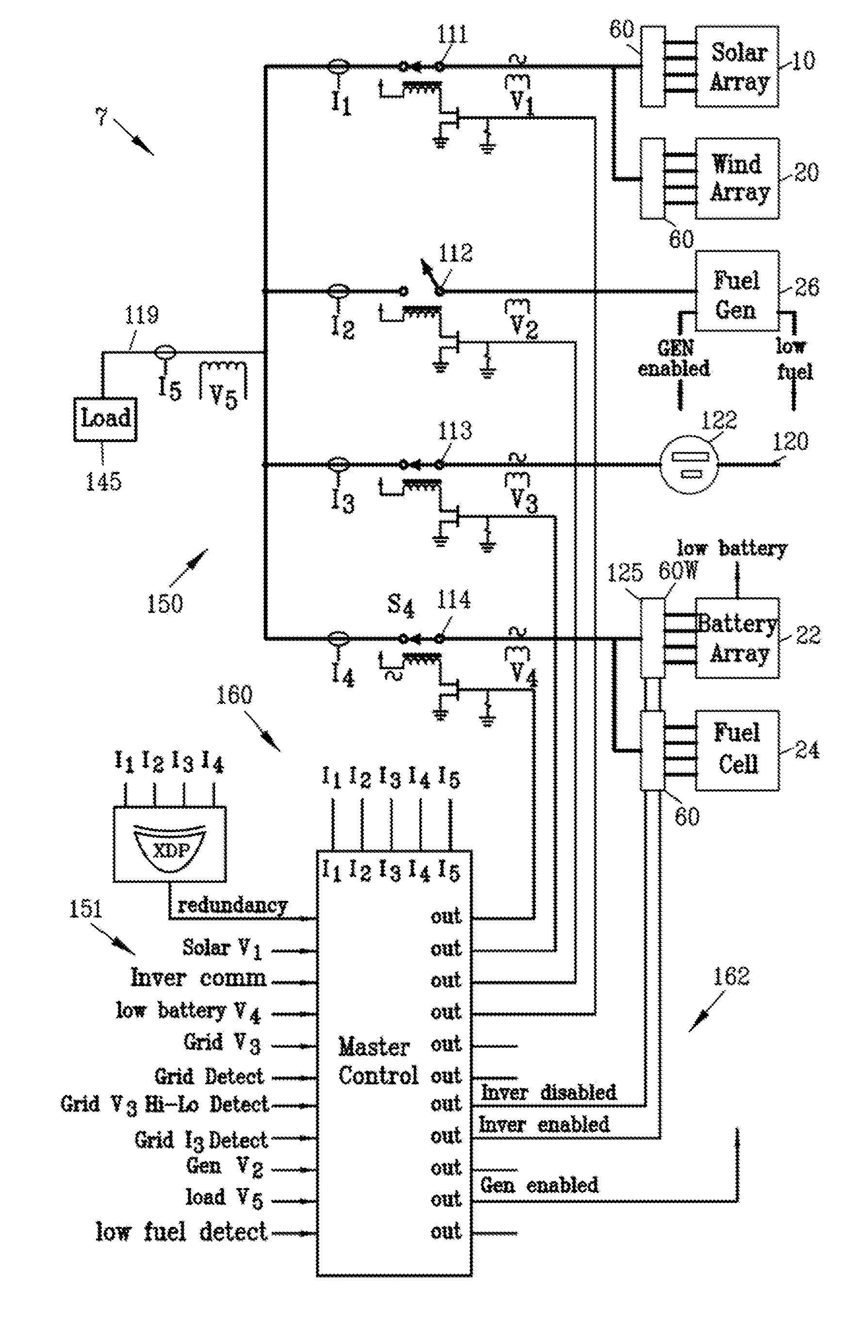
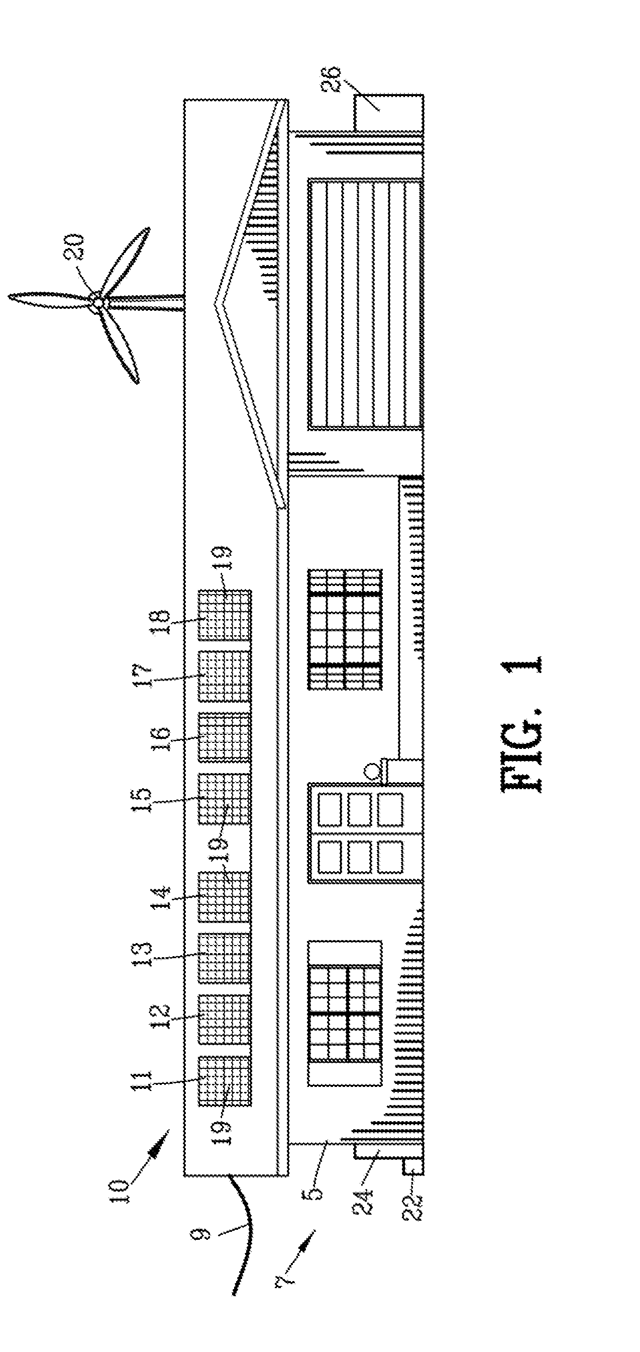
[0081]FIG. 1 is a front view of a building structure 5 incorporating an interface for renewable energy system 7 for interconnecting a plurality of power sources to an AC power grid 9. The plurality of power sources include a photovoltaic solar array 10 and a wind turbine 20. Preferably, the photovoltaic solar array 10 and the wind turbine 20 incorporate an energy storage unit such as a battery array 22 and / or a fuel cell array 24. Preferably a fuel operated generator 26 is incorporated into the system for emergency operation.

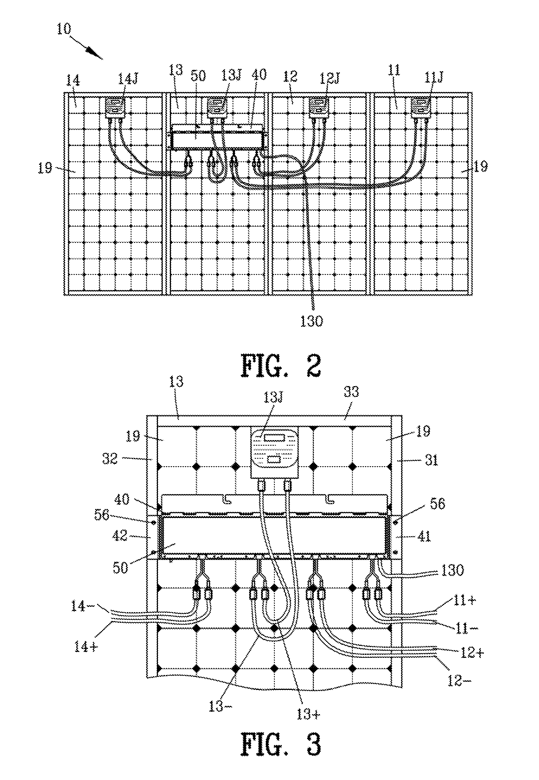
[0082]The photovoltaic solar array 10 is illustrated having a plurality of photovoltaic solar panels 11-18. Although the building structure 5 has been shown as a residential building structure, it should be understood that the photovoltaic solar array 10 may be mounted on virtually any type of building structure as well as being mounted on a ground surface.

[0083]Each of the plurality of photovoltaic solar panels 11-18 is made from a multiplicity of photovoltaic ...


PUM


Abstract

An improved micro-inverter apparatus is disclosed for intelligently controlling energy harvest from photovoltaic solar panels based on one or more adjustable, user-defined variables. The improved micro-inverter apparatus may include a microcontroller configured to monitor the operating temperature of its micro-inverter and control the power harvested from associated solar panels in order to ensure the operating temperature of the micro-inverter does not approach a level that would damage the micro-inverter's circuitry or other components. Similarly, the micro-inverter apparatuses' microcontroller may be configured to monitor the total harmonic distortion of the micro-inverter's AC power output and control the power harvested from associated solar panels in order to ensure the total harmonic distortion of the AC power output does not exceed a threshold level.

Description

BACKGROUND OF THE INVENTION[0001]1. Field of the Invention[0002]This invention relates to solar energy and more particularly to an improved interface for renewable energy systems such as photovoltaic solar panels and the like.[0003]2. Description of the Related Art[0004]The utilization of solar energy extends back to the 7th century B.C., where a magnifying glass was used to make fire. Since then, the evolution of solar technology has progressed from strictly solar to thermal conversion systems to the discovery of the photovoltaic effect in the 1800's.[0005]Advancement of the photovoltaic art continued to progress, and in the 1950's the development of the silicon photovoltaic (PV) cell became the first solar cell capable of producing sufficient power to run simple electrical equipment. In 1964 NASA launched the first Nimbus spacecraft, which was powered by a 470 watt photovoltaic array. In 1981 the first solar powered aircraft had solar cells capable of producing 3,000 watts. In 198...

Claims


Application Information

Patent Timeline
IPC IPC(8): H02J3/38G01K13/00G01R29/26H02M7/537H02S50/10
CPCH02J3/382H02J3/383H02M7/537H02J3/386H02M2001/327G01R29/26G01K13/00H02M1/32H02S50/10H02M7/003H02J2300/24H02J3/381Y02E10/56Y02E10/76H02M1/327H02J2300/26Y02B10/10
Inventor KRAVTIZ, ARNOLDDELLA SERA, ALDO P.
Owner TECH RES
Why Eureka
Try Eureka