Floating offshore structures

Active Publication Date: 2016-08-11
GE RENEWABLE TECH WIND BV
View PDF9 Cites 6 Cited by
  • Summary
  • Abstract
  • Description
  • Claims
  • Application Information

AI Technical Summary

Benefits of technology

[0025]In some examples, the water tanks may comprise at least one one-way valve for increasing the quantity of water in the water tank and at least one-way valve for decreasing the quantity of water in the water tank. The arrangement of one-way valves is a manner for filling and emptying tanks that may reduce the complexity.
[0026]In some

Problems solved by technology

In order for these structures to be stable, the mooring lines must always be under tension, otherwise the offshore structure could become unstable and could fall over.
Since the loads on the offshore structures, and particularly on a floating wind turbine may vary considerably both in magnitude and direction, a high amount of excess buoyancy and hi

Method used


Image

  • Floating offshore structures
  • Floating offshore structures
  • Floating offshore structures

Examples


Embodiment Construction

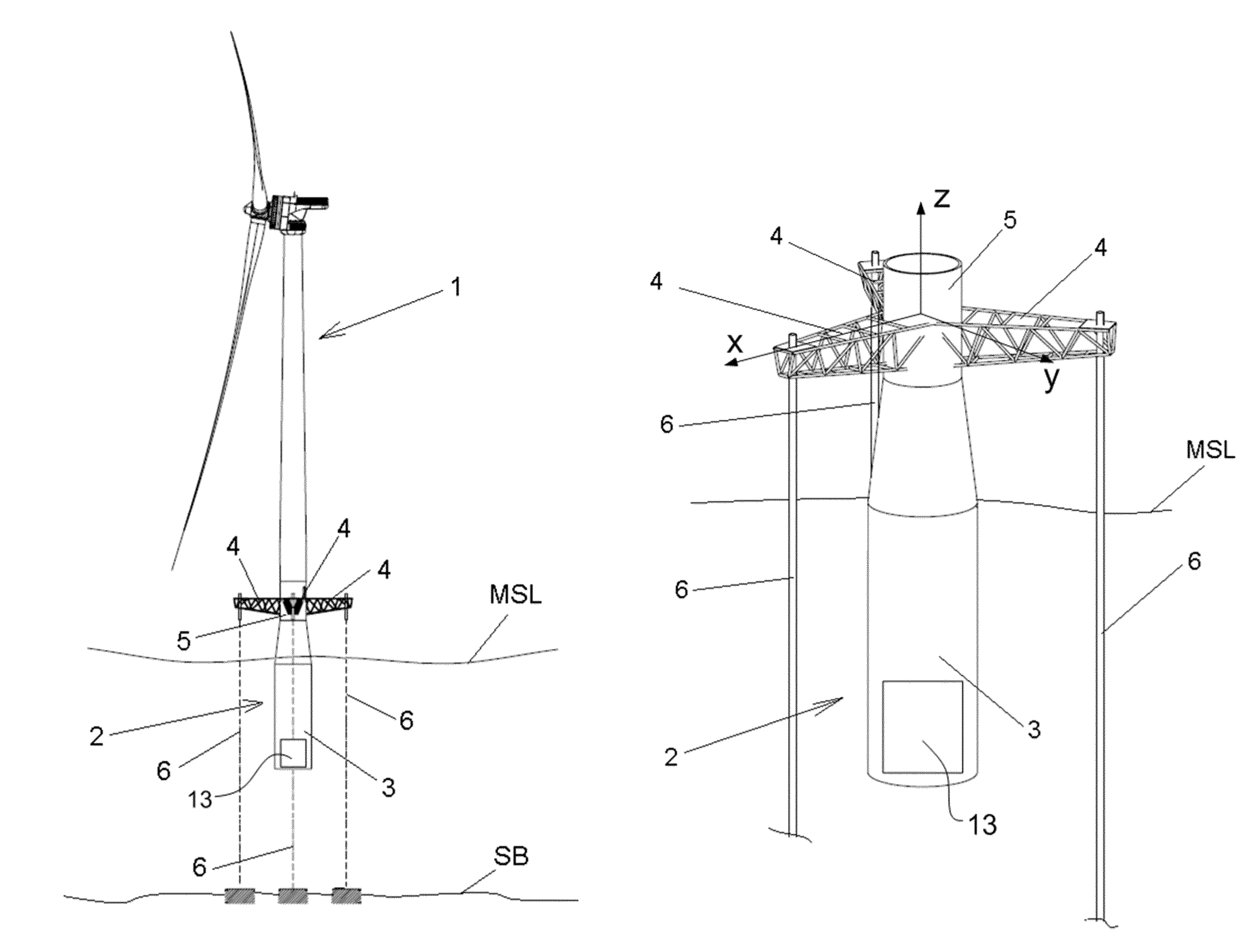
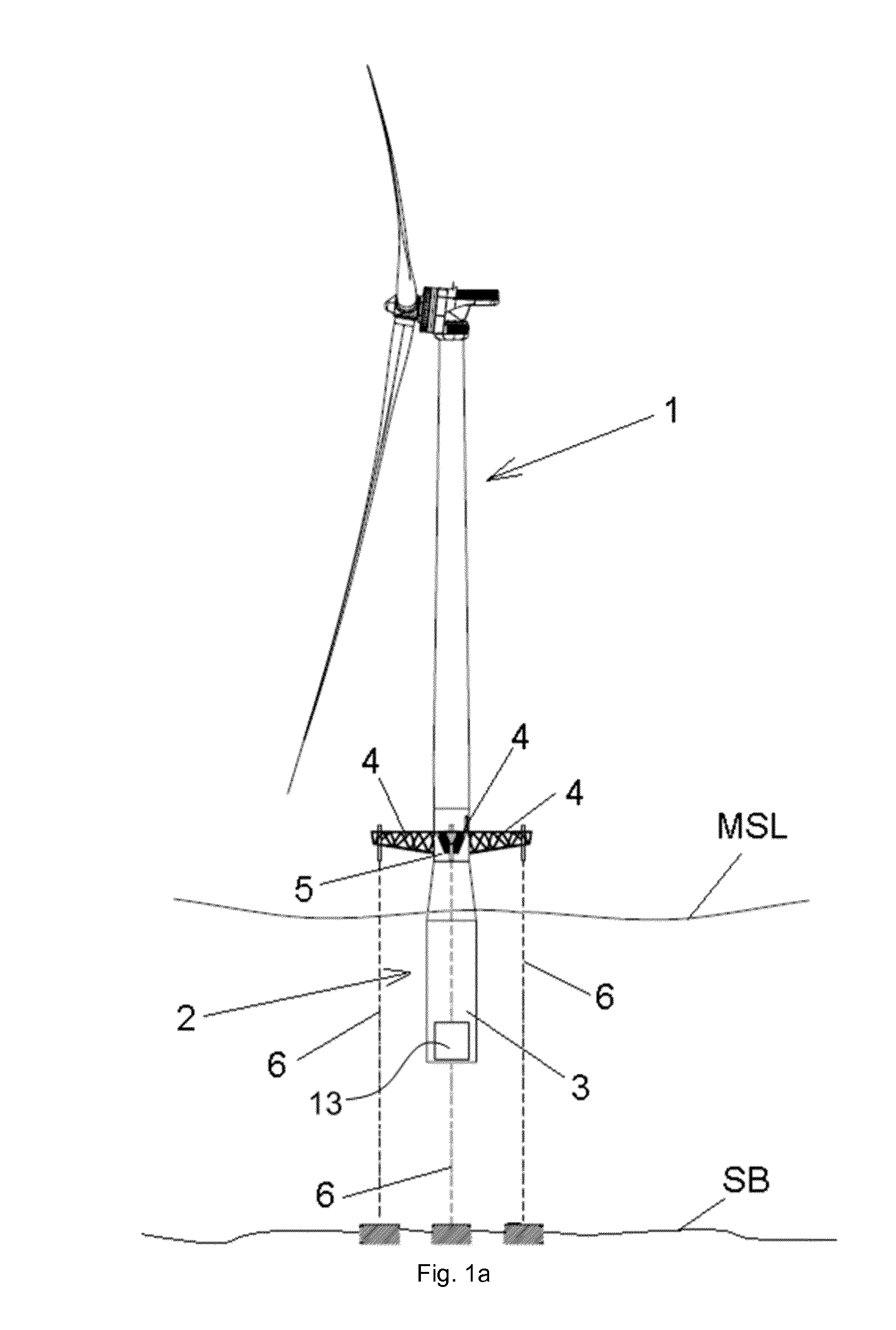
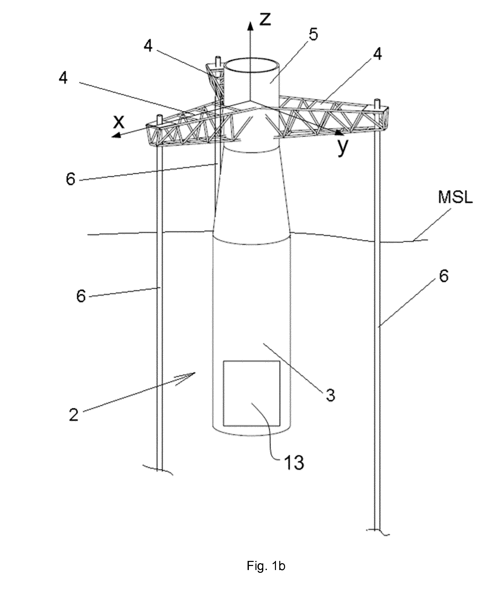
[0038]FIGS. 1a and 1b show an example of an offshore wind turbine, and more particularly a floating wind turbine of the TLP (Tension Leg Platform) type.

[0039]The wind turbine 1 may comprise a buoyancy structure 2, with at least one floater tank 3. The buoyancy structure 2 may be designed such as to remain submerged in a position above the sea bed SB and below the mean sea level MSL, to provide an upward thrust for supporting the weight of the wind turbine and other loads.

[0040]In order to stabilize a floating wind turbine with such a buoyancy structure, ie in order to restrain within acceptable limits its 6 degrees of freedom (surge, sway, heave, pitch, roll and yaw), the mooring lines are put under tension by the excess buoyancy provided by the floater tanks.

[0041]Examples of the present invention may also be applied to taught leg buoy (TLB) wind turbines and other offshore structures. In particular, examples of the present invention may be applied to any offshore structure with te...


PUM


Abstract

Methods for controlling tension in mooring lines of a floating offshore structure having a buoyancy structure including one or more water tanks and the buoyancy structure providing excess buoyancy are provided. The methods comprise varying the mass and/or the centre of gravity of the floating offshore structure by varying the quantity of water in one or more of the water tanks. Also, floating offshore structures are disclosed, the structures comprising a buoyancy structure having one or more floater tanks providing excess buoyancy, and a plurality of tensioned mooring lines, and further comprising a control system for increasing and decreasing a quantity of water in one or more of the floater tanks. Also, possible uses of floating offshore structures are provided wherein under standard operating conditions, the floater tanks are at least partially filled with water.

Description

[0001]This application claims the benefit of European Patent Application EP13382123.1 filed 28 Mar. 2013.[0002]The present disclosure relates to floating offshore structures.BACKGROUND ART[0003]Floating offshore structures such as e.g. oil platforms, offshore wind turbines, and offshore meteorological towers are known.[0004]Several configurations have been proposed for the floating or buoyancy structures: many of these employ floater elements in the form of substantially hollow floater tanks that in use are arranged substantially below the mean sea level and provide a buoyancy force to support the structure, e.g. a wind turbine. Ballast and / or mooring lines anchored to the seabed are provided for achieving stability.[0005]In some of these floating structures, the buoyancy structure is designed to provide an excess buoyancy force and is maintained floating under the mean sea level by taut mooring lines tensioned by the excess buoyancy force.[0006]For example, concepts have been devel...

Claims


Application Information

Patent Timeline
IPC IPC(8): B63B22/20B63B21/50F03D13/25B63B35/44
CPCB63B21/502F05B2240/95E02B2017/0091B63B2035/446F03D13/22F05B2240/93F03D13/25B63B21/50B63B22/20B63B35/44Y02E10/727Y02E10/72
Inventor BERGUA, ROGER
Owner GE RENEWABLE TECH WIND BV
Why Eureka
Try Eureka