Heater member and substrate processing apparatus having the same

a technology of substrate processing and heater member, which is applied in the direction of coating, chemical vapor deposition coating, metallic material coating process, etc., can solve the problems of heat loss and increase of substrate amount processed on the susceptor, temperature decline phenomenon, and deterioration of productivity, so as to reduce the variation of temperature distribution, improve temperature uniformity, and reduce heat loss

Inactive Publication Date: 2016-08-11
KOOKJE ELECTRIC KOREA
View PDF0 Cites 1 Cited by
  • Summary
  • Abstract
  • Description
  • Claims
  • Application Information

AI Technical Summary

Benefits of technology

[0024]According to an embodiment of the inventive concepts, a variation of temperature distribution can be minimized.
[0025]According to an embodiment of the inventive concepts, thermal efficiency can be elevated.
[0026]According to and embodiment of the inventive concepts, temperature uniformity can be improved.
[0027]According to an embodiment of the inventive concepts, it can be prevented that drooping and twisting of a heating wire by thermal expansion of the heating wire.
[0028]According to an embodiment of the inventive concepts, it can be prevented that corrosion of the heating wire by process gas.

Problems solved by technology

The atomic layer deposition method forms a deposition layer with desired thickness by repeating units of a reaction cycle by which a layer is deposited at about atomic layer thickness, but the atomic layer deposition method is lower than a chemical vapor deposition (CVD) method or a sputtering method in deposition rate and requires a lot of time for growing a layer of desired thickness, thereby productivity is deteriorated.
However, a temperature declining phenomenon is occurred by a heat loss and an increase of substrate amount processed on the susceptor.
In additional, corrosion of heater is occurred by a process gas permeation and performance deterioration of heater is occurred by an oxide deposition.

Method used


Image

  • Heater member and substrate processing apparatus having the same
  • Heater member and substrate processing apparatus having the same
  • Heater member and substrate processing apparatus having the same

Examples


embodiment

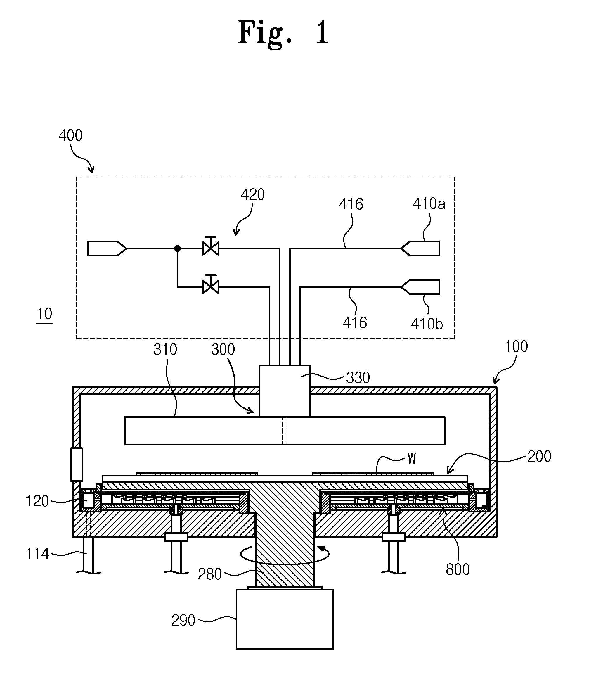
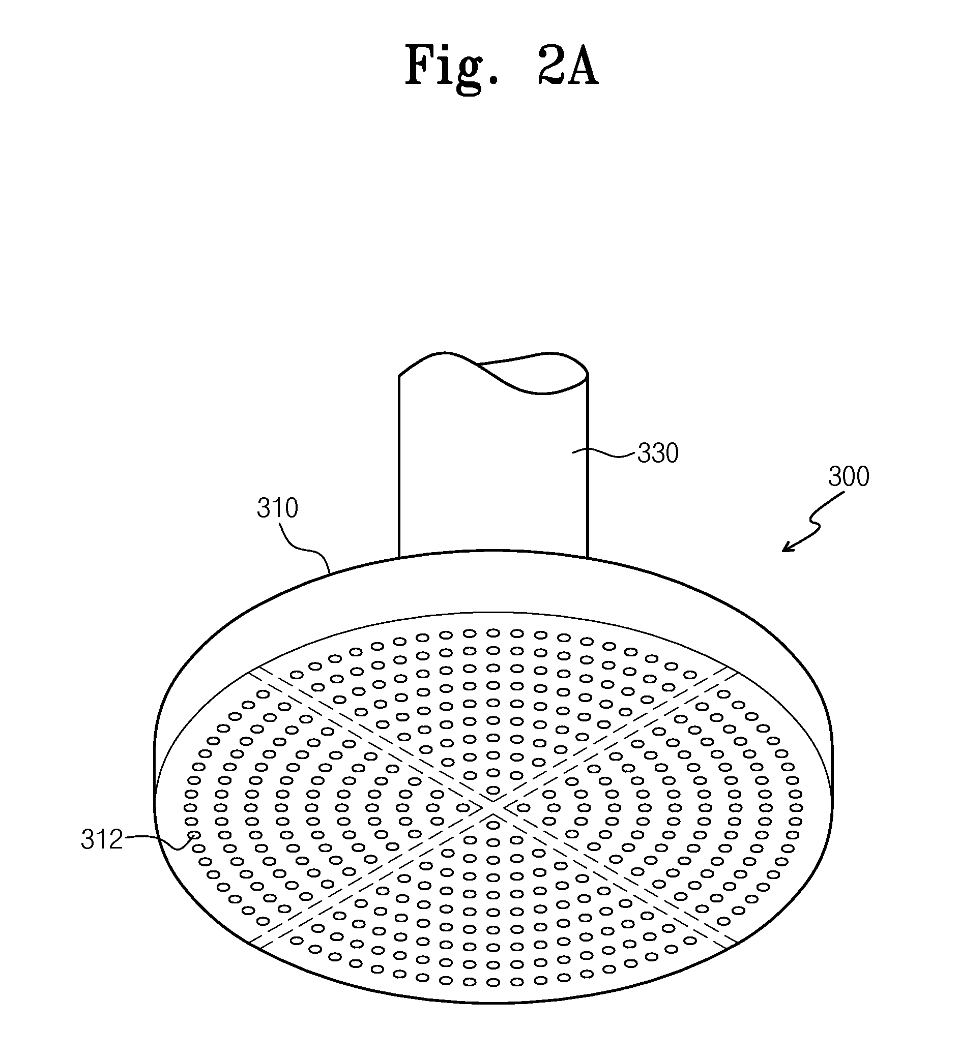
[0037]FIG. 1 illustrates an atomic layer deposition apparatus according to an embodiment of the inventive concepts. FIGS. 2a and 2b are a perspective view and a cross sectional view illustrating a spay member of FIG. 1. FIG. 3 is a perspective view illustrating a substrate susceptor of FIG. 1.

[0038]Referring to FIGS. 1 to 3, the atomic layer deposition apparatus 10 may include a process chamber 100, a substrate susceptor 200 which is a support member, a splay member 300, a supply member 400 and a heater member 800.

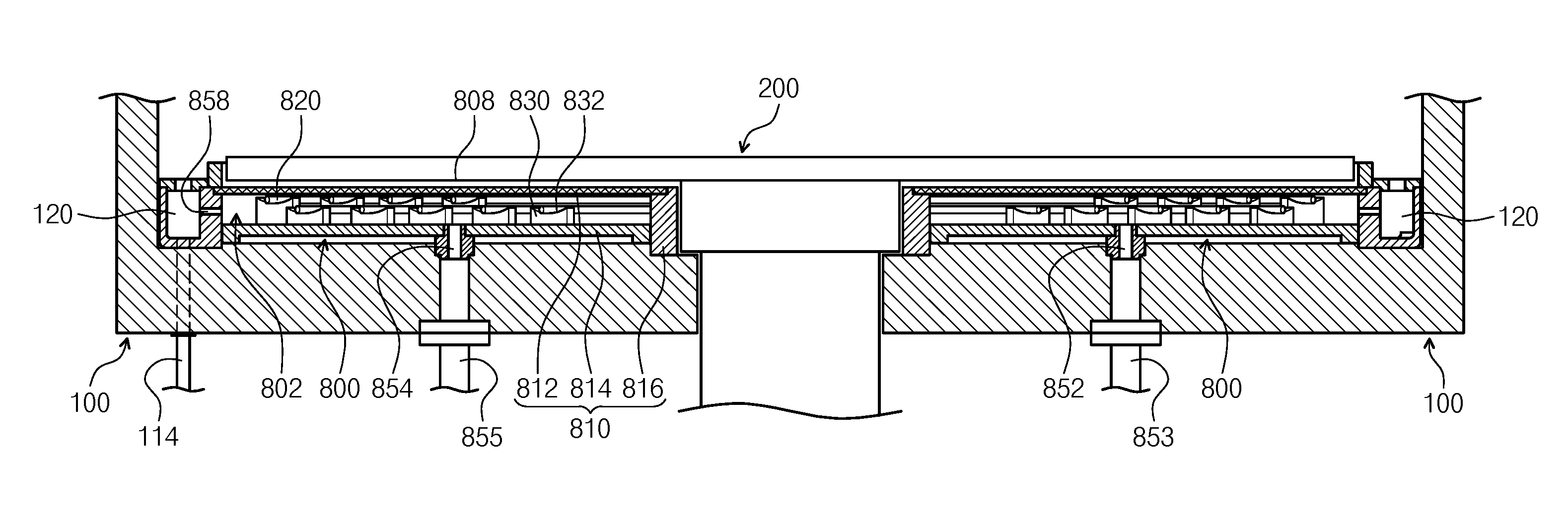
[0039]A gate 112 may be provided to a side of the process chamber 100. Substrates W may be loaded in and out through the gate 112 for processes. The process chamber 100 may include an exhaust duct 120 and an exhaust pipe 114 on the edge of its lower portion to exhaust reaction gas and purge gas supplied to the process chamber and a byproduct produced in an atomic layer deposition process. The exhaust duct 120 may be formed of ring shape which locates at the outside of the ...


PUM

PropertyMeasurementUnit
thermal expansionaaaaaaaaaa
flexibilityaaaaaaaaaa
heataaaaaaaaaa

Abstract

The present invention relates to a substrate processing apparatus. The substrate processing apparatus according to the present invention comprises: a processing chamber; substrate susceptor, installed in the processing chamber, which rotates in connection with a rotary shaft, a plurality of substrates being disposed on the same plane thereof; a heater member located on the lower surface of the substrate susceptor; and a spraying member for spraying a gas onto the entire processing surface of the substrate at a position corresponding to each of the plurality of substrates disposed on the substrate susceptor, wherein the heater member has an inner space in which heating wires for heating the substrate susceptor are arranged in a plurality rows of verticality and horizontality in a concentric circle based on the rotary shaft of the substrate susceptor.

Description

TECHNICAL FIELD[0001]The present invention relates to a substrate processing apparatus, and more specifically relates to a substrate processing apparatus having a heater member.BACKGROUND ART[0002]In a deposition process for manufacturing semiconductor devices, an atomic layer deposition method has been introduced to improve conformability of a deposition layer. The atomic layer deposition method forms a deposition layer with desired thickness by repeating units of a reaction cycle by which a layer is deposited at about atomic layer thickness, but the atomic layer deposition method is lower than a chemical vapor deposition (CVD) method or a sputtering method in deposition rate and requires a lot of time for growing a layer of desired thickness, thereby productivity is deteriorated.[0003]Particularly, temperature uniformity of a susceptor is one of essential factors which determines thickness uniformity of the layer deposited on a substrate. However, a temperature declining phenomeno...

Claims


Application Information

Patent Timeline
Patent Type & Authority Applications(United States)
IPC IPC(8): C23C16/48C23C16/458C23C16/44C23C16/455
CPCH01L21/67109H01L21/68764H01L21/68771C23C16/45565C23C16/481C23C16/4412C23C16/45544C23C16/4585C23C16/4584C23C16/45519H01L21/205H01L21/683
Inventor BANG, HONG JOOKIM, SANG YEONSHIN, DONG HWAKIM, MIN SEOKYANG, JIN YOUNG
Owner KOOKJE ELECTRIC KOREA
Why Eureka
Try Eureka