
Expandable LNG processing plant

a technology of liquefied natural gas and processing plant, which is applied in the direction of cold treatment separation, gas handling/storage effect, solidification, etc., can solve the problems of increasing the cost of traditional onshore lng storage and offloading facilities, affecting the overall installation cost of lng projects, and affecting the capacity of the plant. , to achieve the effect of expanding the plant capacity

Inactive Publication Date: 2016-08-11
WOODSIDE ENERGY TECH PTY LTD
View PDF5 Cites 11 Cited by
  • Summary
  • Abstract
  • Description
  • Claims
  • Application Information

AI Technical Summary

Benefits of technology

The present invention provides an LNG processing plant that can be positioned on a structure at a processing location adjacent to a body of water. The plant includes a first phase LNG processing plant with a pre-determined capacity and a second phase facility that can be added to increase the plant's capacity. The second phase facility can be added on the deck of the structure or offshore. The plant also includes a cryogenic storage tank for LNG and a transfer facility for loading and unloading LNG between the tank and an LNG carrier. The plant can be transported from one location to another and is suitable for use as an LNG production plant. The technical effects of the invention include increased flexibility and efficiency in LNG processing and production.

Problems solved by technology

The costs associated with the construction and installation of a jetty to allow berthing of an LNG Carrier is a major cost.
The cost of traditional onshore LNG storage and offloading facilities has continued to increase through the years and is now a very significant component of the total installed cost for an LNG project.
Given their size and complexity, the costs associated with the implementation of a complete LNG liquefaction plant at sea are extremely high.
The cost of LNG storage and offloading facilities has continued to increase through the years and is now a very significant component of the total installed cost for an LNG project.

Method used


Image

  • Expandable LNG processing plant
  • Expandable LNG processing plant
  • Expandable LNG processing plant

Examples


first embodiment

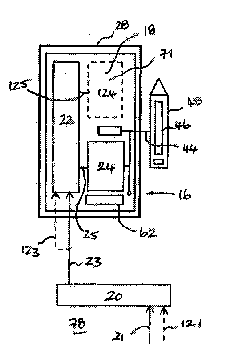
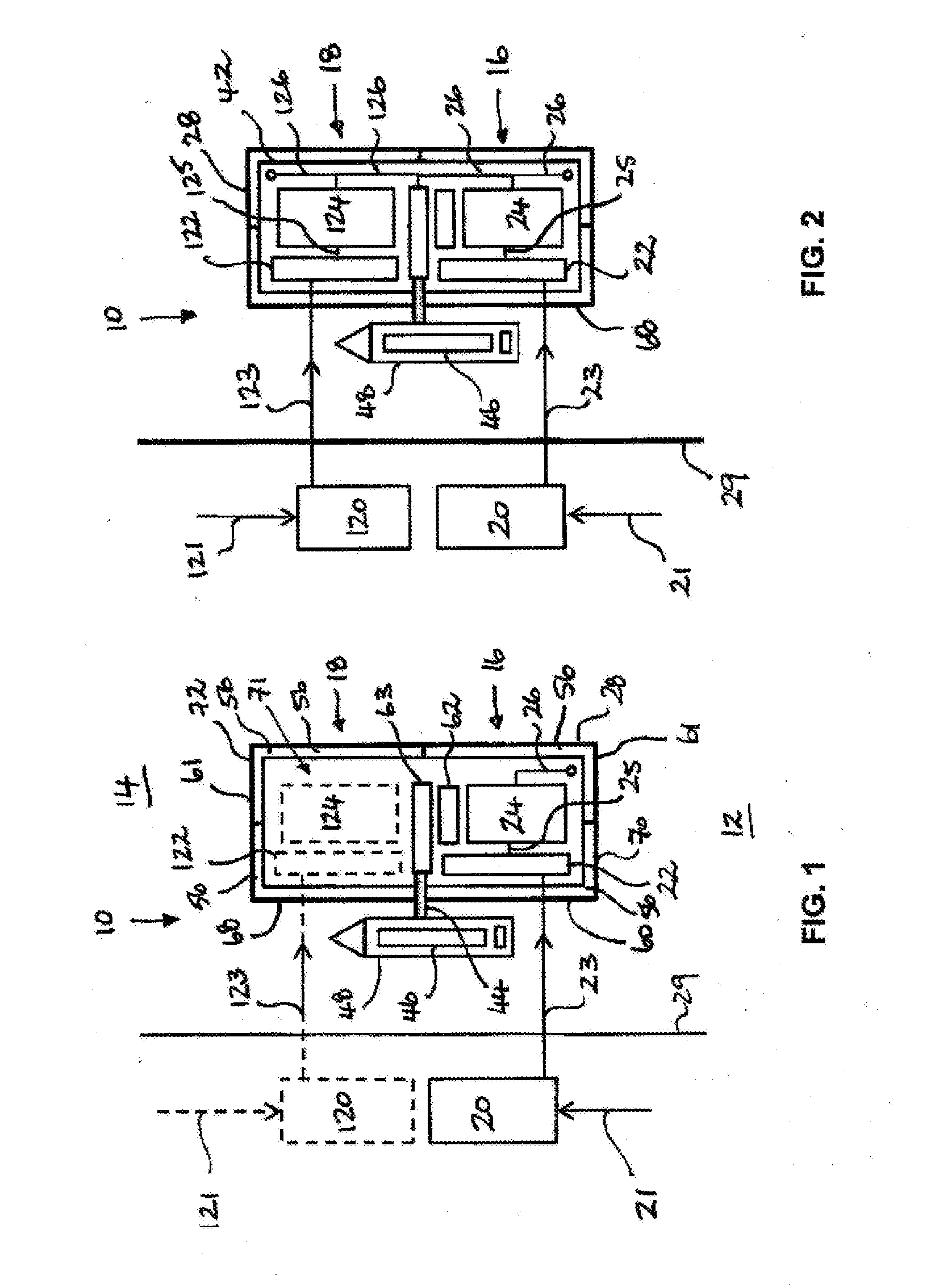
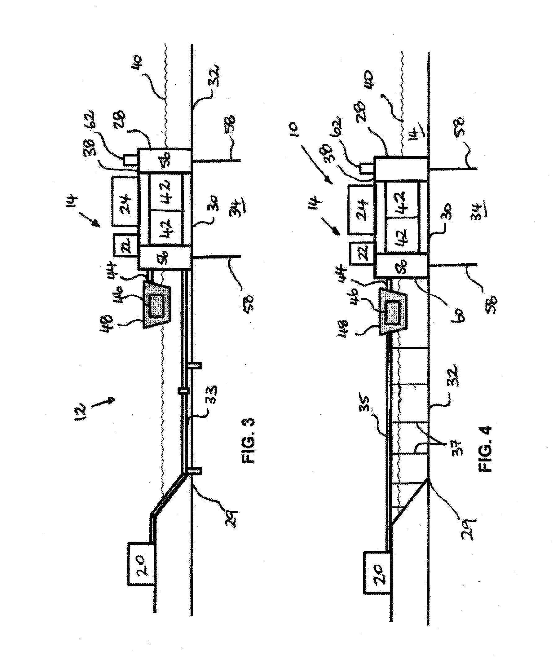
[0075]the present invention is now described with reference to FIGS. 1 to 4 in the context of the LNG processing plant being an LNG production plant. More specifically, there is provided a first phase LNG production plant for producing an initial plant capacity of LNG, the first phase LNG production plant comprising a plurality of spaced-apart facilities, each facility provided with plant equipment related to a pre-determined function associated with the liquefaction of LNG. The first phase LNG production plant includes at least the following facilities:[0076]a) a gas receiving facility for receiving a hydrocarbon stream comprising hydrocarbon gas and liquids and separating the liquids, including one or both of condensate and free water, from the hydrocarbon stream to produce a hydrocarbon feed gas stream for a gas pre-treatment facility;[0077]b) a gas pre-treatment facility for receiving a hydrocarbon feed gas stream from the gas receiving facility and removing contaminants from th...

second embodiment

[0100]the present invention is now described with reference to FIGS. 6 and 7 for which like reference numerals refer to like parts. As for FIGS. 1 and 2, the first phase LNG production plant 16 is shown in solid lines in FIG. 6 and FIG. 7 whilst the second phase LNG production plant 18 is shown in dotted lines in FIG. 6 with solid lines indicating that expansion has been completed in FIG. 7. The dotted lines in FIG. 6 represent the pre-allocated space 71 provided on the deck 38 of the structure 28 for subsequent expansion. In this embodiment the first phase gas receiving facility 20 is arranged on the deck 38 of the structure 28 with a pre-allocated space 71 being provided on the deck 38 of the structure 28 in anticipation of the subsequent addition of the second phase gas receiving facility 120 to be installed at a later time when expansion of the plant capacity is desired. The pre-allocated space 71 is arranged towards a first side 81 of the structure 28 with the pre-allocated spa...

third embodiment

[0101]the present invention is now described with reference to FIGS. 8 to 10 for which like reference numerals refer to like parts. As for FIGS. 1 and 2, the first phase LNG production plant 16 is shown in solid lines in FIGS. 8 to 10 whilst the second phase LNG production plant 18 is shown in dotted lines. The dotted lines in FIGS. 8 to 10 represent the pre-allocated space 71 provided on the deck 38 of the structure 28 for subsequent expansion. In this embodiment, the first phase gas receiving facility 20 is designed and sized of sufficient capacity to produce both the first phase hydrocarbon feed gas stream 23 and the second phase hydrocarbon feed gas stream 123. In other words, the first phase gas receiving facility 20 is capable not only of operating at the initial plant capacity prior to expansion, but is also capable of operating at the maximum plant capacity after one or more additional units are added to provide the second phase production plant 18. In FIG. 8, the first phas...


PUM


Abstract

An LNG processing plant positioned at a processing location adjacent to a body of water is described. The LNG processing plant includes A) a first phase LNG processing plant for processing an initial plant capacity of LNG, the first phase LNG processing plant including a plurality of first phase facilities, each first phase facility provided with plant equipment related to a pre-determined function associated with the processing of LNG, wherein one or more of the plurality of first phase facilities is arranged on a deck of a structure wherein the deck is arranged above the level of the water at a selected offshore or near-shore location; and, B) one or more second phase facilities provided on the deck of the structure to provide a second phase LNG processing plant, said second phase LNG processing plant having a maximum plant capacity that is higher than the initial plant capacity.

Description

FIELD OF THE INVENTION[0001]The present invention relates to an expandable liquefied natural gas (LNG) processing plant. More particularly, some embodiments of the invention are related to LNG production plants. Other embodiments of the invention are related to natural gas regasification plants.BACKGROUND TO THE INVENTION[0002]Large volumes of natural gas (i.e., primarily methane) are located in remote areas of the world. This gas has significant value if it can be economically transported to market. Natural gas (“NG”) is routinely transported from an onshore LNG production plant to another location in its liquid state as liquefied natural gas (“LNG”) by way of loading the LNG in the cryogenic storage tanks of purpose built large ocean going vessels known as “LNG Carriers”. Liquefaction of the natural gas makes it more economical to transport as LNG occupies only about 1 / 600th of the volume than the same amount of natural gas does in its gaseous state. Prior to liquefaction, raw nat...

Claims


Application Information

Patent Timeline
Patent Type & Authority Applications(United States)
IPC IPC(8): F25J1/00
CPCB63B2035/448F17C2221/033F17C2221/035F17C2265/05F17C2270/0123F25J1/0022F25J2290/60F25J1/0271F25J1/0274F25J1/0278F25J2220/60F25J2220/64F25J2220/66F25J1/0269
Inventor FAKA, SOLOMON ALADJA
Owner WOODSIDE ENERGY TECH PTY LTD
Learn More