Apparatus and method for tracking defects in sheet materials

a technology of sheet materials and apparatus, applied in the field of apparatus and method for tracking defects in sheet materials, can solve the problems of difficult to reliably and consistently determine, by calculation, the expected location of material defects downstream in processing, and the inability to determine the position of material defects with certainty, etc., to achieve the effect of easing the burden on the apparatus, reducing the burden on the memory unit, and reducing the cost of the method

Active Publication Date: 2016-08-11
KHS GMBH
View PDF9 Cites 8 Cited by
  • Summary
  • Abstract
  • Description
  • Claims
  • Application Information

AI Technical Summary

Benefits of technology

[0050]By way of the combination of the position determination with the identification, a perceptible easing of the burden on the apparatus used for the method is therefore achieved, in one possible embodiment for the sensors, memory unit, and, as appropriate, a control unit, which in turn leads to an economical performance of the method.
[0051]In order to ease the burden on the memory unit and to ensure or essentially ensure or promote reliable performance of the method, it is further possible for the data records stored in the memory unit to be deleted from the memory unit after the processing of the sheet section.

Problems solved by technology

As a result of this, the markings which have been applied, which identify the material defect, are frequently altered or removed, such that the position of the material defect cannot be determined with certainty.
Such calculation systems, however, are extremely imprecise, and with sheet materials, which, for example, are stretched or shrunk during the processing, are highly unreliable, such that reliable location of the material defect cannot be effected, or, for the processing of the material defects, it may be necessary and / or desired for substantially larger sheet sections to be processed.
In other words, there are different factors that can make it difficult to reliably and consistently determine, by calculation, the expected location of the material defect downstream in processing.
Some sheet materials, such as plastic film, may stretch or shrink during processing or handling of the sheet material.
Thus, if the calculation is erroneous or sufficiently imprecise, as can often be the case with many calculation systems, the defect-processing station will process a section of material that does not contain a defect, which is undesirable.
Not only will sheet material of acceptable quality be processed, such as by removal, but the defect will remain in the sheet material that proceeds on for further use.
Obviously, such waste of acceptable material and failure to process defective material is undesirable.
In addition, if the material is generally prone to stretching or shrinking during handling, the section of the sheet material containing the defect will either arrive earlier or later at the defect-processing station than would be expected by the calculation.
As a result of the imprecision of calculation and / or variability in the characteristics of the sheet material, larger amounts of material often must be processed in order to compensate for the imprecision, which can be wasteful.
If the deviations between the data records are too great, however, there is the risk that, when the detection of the surface structure features starts again, sections will be identified as being concurrent which do not involve a section with a material defect.
In this situation, however, undesirable changes to the surface may occur, which, for example, also may affect the surface structure features which have been acquired.
Thus, for example, friction, dirt contamination, or the like may occur, which can change surface structure features.
In such a situation, the data obtained by the second marking sensor regarding the surface structure would be insufficient to perform a comparison.
The expenditure for a permanent or substantially permanent detection is very high, however, since extremely high data quantities must be or should be processed.

Method used


Image

  • Apparatus and method for tracking defects in sheet materials
  • Apparatus and method for tracking defects in sheet materials

Examples


Embodiment Construction

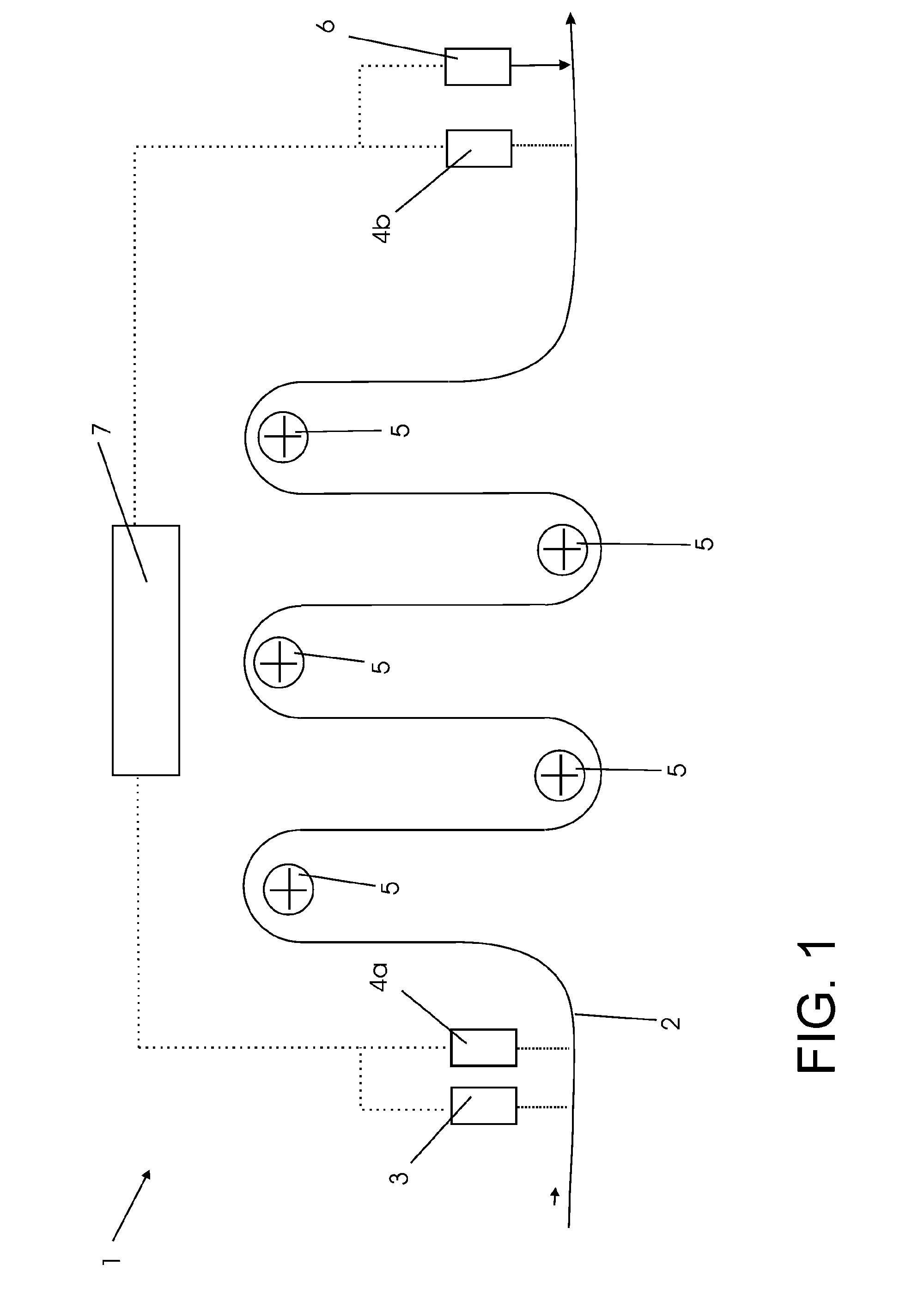
[0072]FIG. 1 shows a sheet material 2, which is guided through an apparatus 1 for the marking, detection, and processing of a material defect in a sheet material. The sheet material 2 is a steel strip. The apparatus 1 further comprises an optical sensor 3, for example a line scanning camera, which is designed for the detection of defects, such as micro-cracks, in the surface of the sheet material 2.

[0073]Downstream of the optical sensor 3 in the direction of run of the strip is a first marking sensor 4a, which is a laser scatter light measuring device, designed in such a way as to carry out what is referred to as the LSA process.

[0074]The apparatus 1 further comprises a plurality of deflection rollers 5, around which the sheet material 2 is guided. For the detection of the position of the material defect, a second marking sensor 4b is put into arrangement, which is likewise designed as a laser scatter light measuring device.

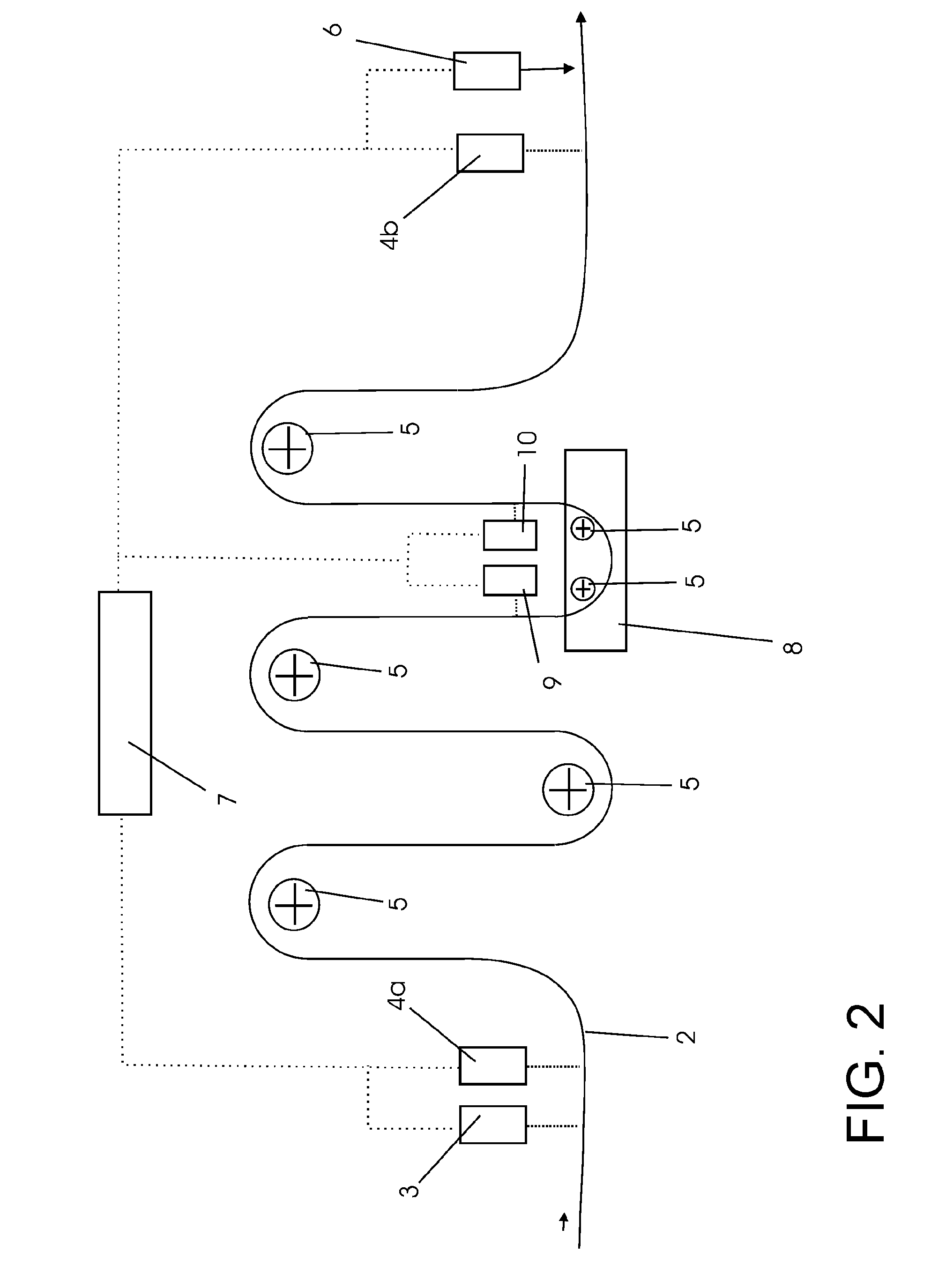
[0075]Following in the direction of run of the sheet, arran...


PUM

PropertyMeasurementUnit
lengthaaaaaaaaaa
heightaaaaaaaaaa
lengthaaaaaaaaaa

Abstract

An apparatus and method for tracking defects in sheet materials. The abstract of the disclosure is submitted herewith as required by 37 C.F.R. §1.72(b). As stated in 37 C.F.R. §1.72(b): A brief abstract of the technical disclosure in the specification must commence on a separate sheet, preferably following the claims, under the heading “Abstract of the Disclosure.” The purpose of the abstract is to enable the Patent and Trademark Office and the public generally to determine quickly from a cursory inspection the nature and gist of the technical disclosure. The abstract shall not be used for interpreting the scope of the claims. Therefore, any statements made relating to the abstract are not intended to limit the claims in any manner and should not be interpreted as limiting the claims in any manner.

Description

CONTINUING APPLICATION DATA[0001]This application is a Continuation-In-Part application of International Patent Application No. PCT / EP2014 / 066630, filed on Aug. 1, 2014, which claims priority from Federal Republic of Germany Patent Application No. 10 2013 108 485.0, filed on Aug. 6, 2013. International Patent Application No. PCT / EP2014 / 066630 was pending as of the filing date of this application. The United States was an elected state in International Patent Application No. PCT / EP2014 / 066630.BACKGROUND[0002]1. Technical Field[0003]The present application relates to an apparatus and method for tracking defects in sheet materials.[0004]2. Background Information[0005]Background information is for informational purposes only and does not necessarily admit that subsequently mentioned information and publications are prior art.[0006]The present application relates to a method and an apparatus for marking a material defect in a sheet material.[0007]During the processing of sheet materials,...

Claims


Application Information

Patent Timeline
Patent Type & Authority Applications(United States)
IPC IPC(8): G01N21/88G01N21/958G01N21/86
CPCB65H26/066G01N2201/06113B65H2511/512B65H2511/52B65H2553/42B65H2553/45B65H2557/51B65H2557/62B65H2557/64B65H2701/12B65H2701/173G01N21/86G01N21/8851G01N21/958G01N2021/8663G01N2021/888B65H26/02
Inventor HERRMANN, JÜRGEN-PETERHERRMANN, MARIUS MICHAELSCHORN, WOLFGANG
Owner KHS GMBH
Why Eureka
Try Eureka