

Magnetic resonance imaging apparatus and imaging parameter setting assisting method
a technology of magnetic resonance imaging and imaging parameters, applied in the field of magnetic resonance imaging, to achieve the effect of adjusting imaging parameters more efficiently
- Summary
- Abstract
- Description
- Claims
- Application Information
AI Technical Summary
Benefits of technology
Problems solved by technology
Method used
Image

Examples
first embodiment
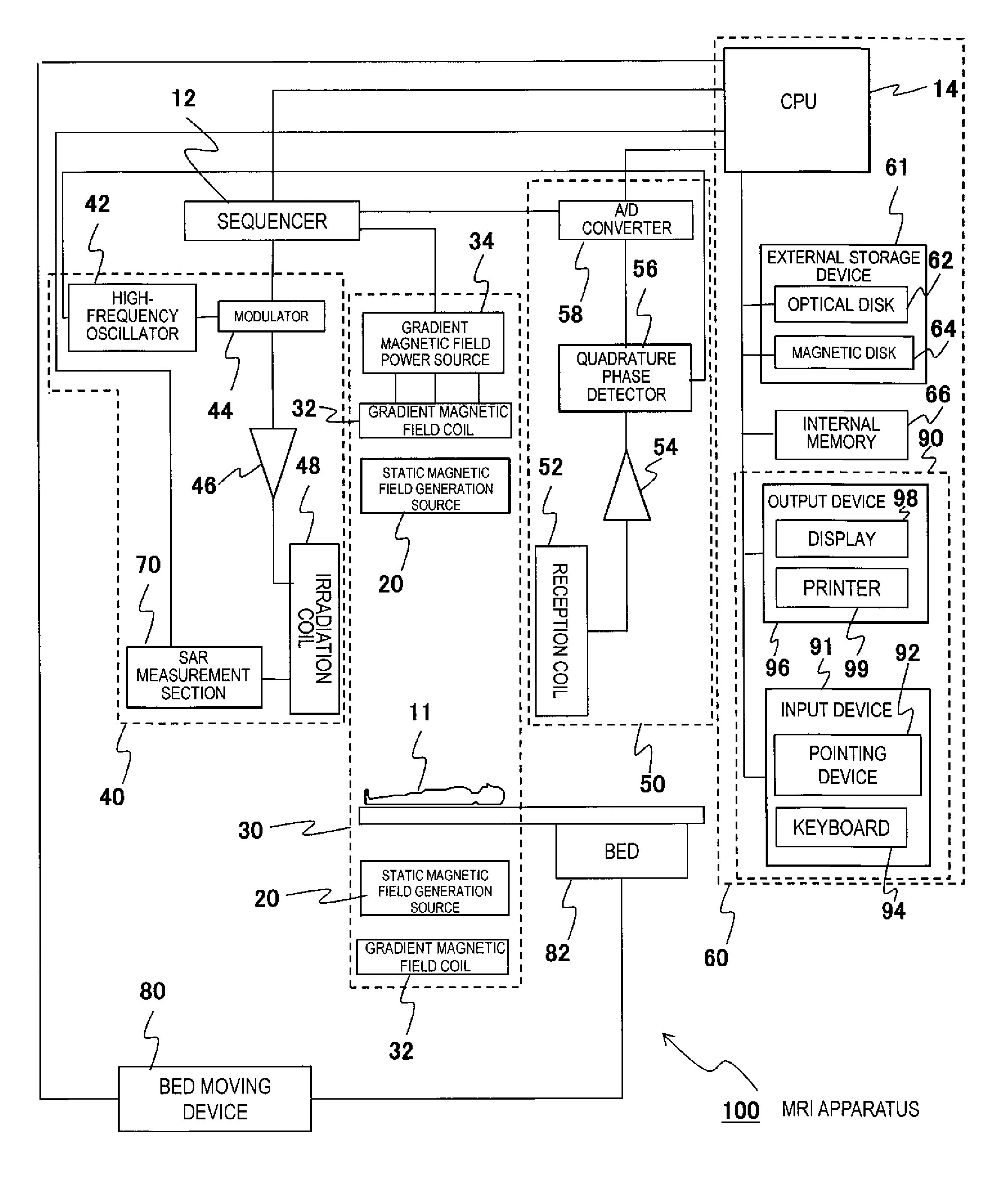
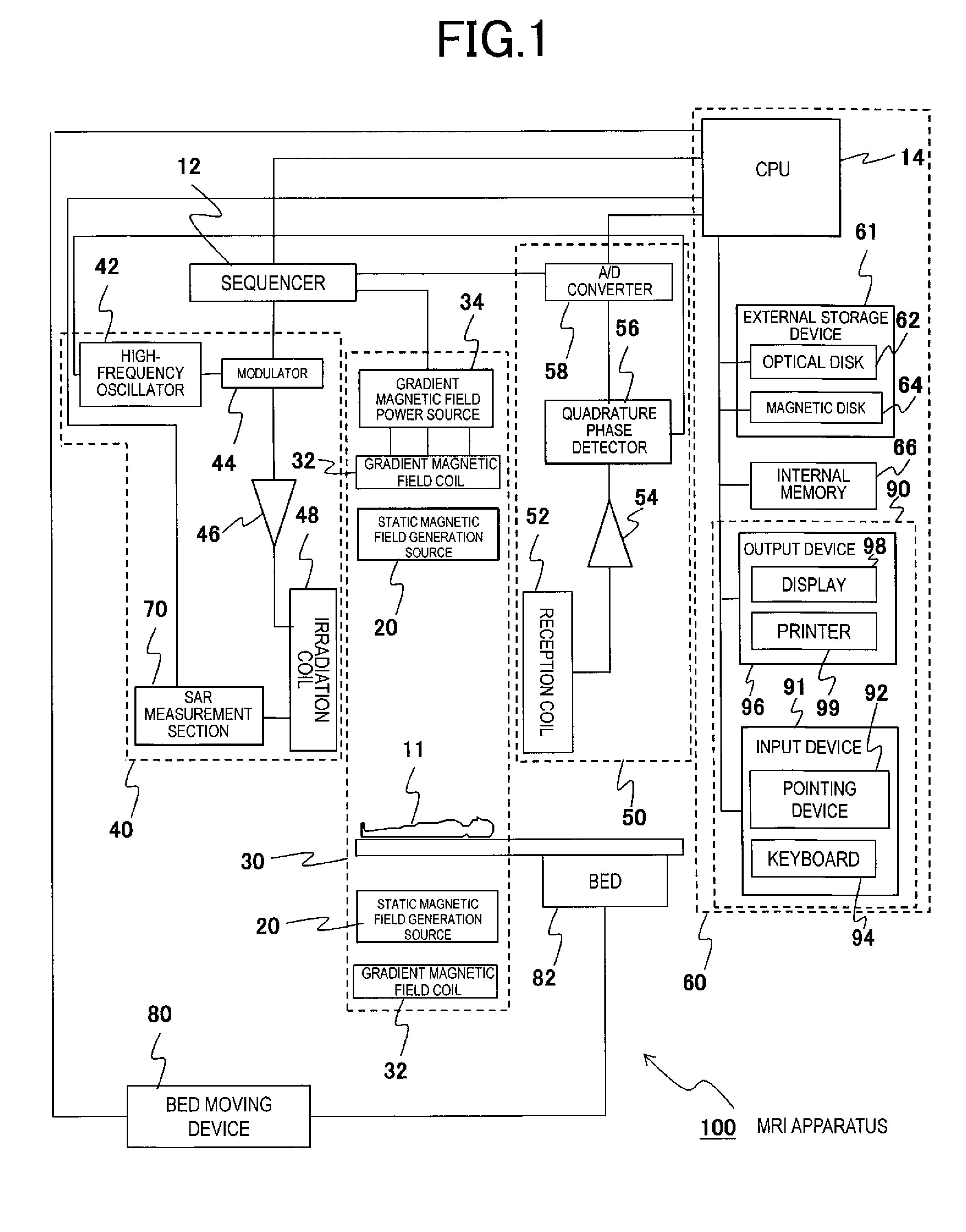
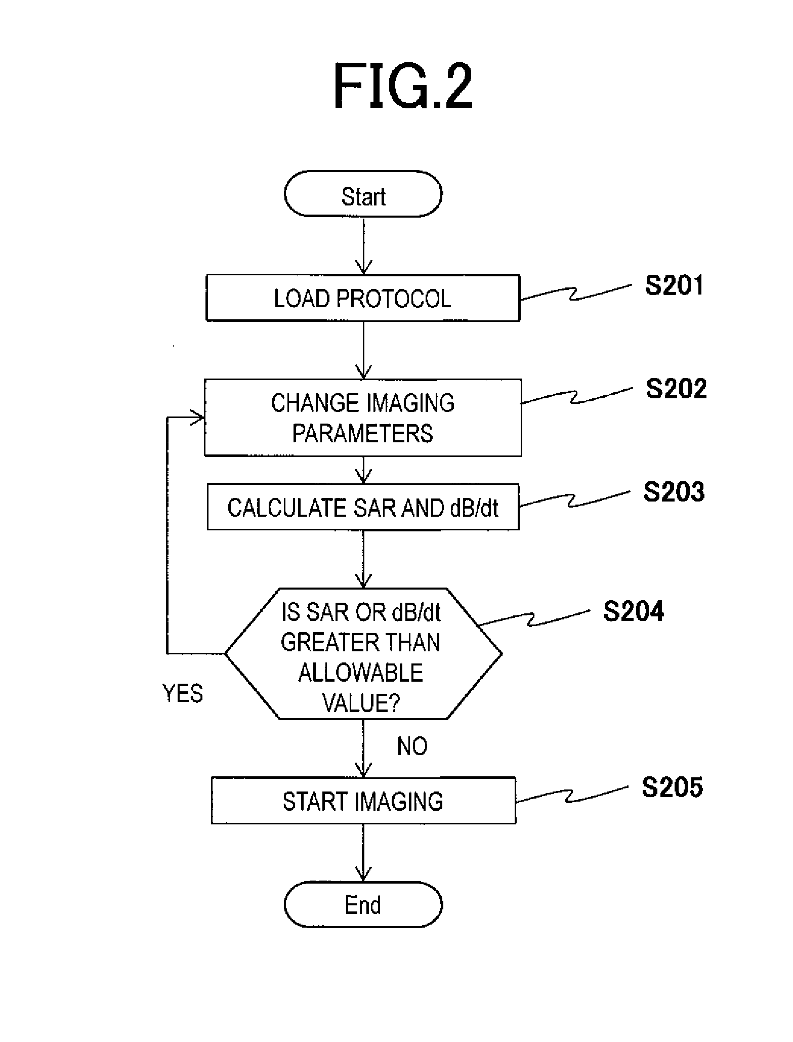
[0054]The first embodiment 1 of the present invention will be described. First of all, the flow before starting imaging using the MRI apparatus 100 with the above configuration will be described with FIG. 2. For the object 11 to be examined, imaging can be started because imaging conditions are satisfied in a case where values of imaging indexes (a SAR and a dB / dt) are within allowable values in an operation mode capable of imaging when an RF pulse that is an electromagnetic wave is irradiated according to the pulse sequence stored in the internal memory 66 and the like of the MRI apparatus 100.
[0055]First, a protocol that is a pair of pulse sequences is loaded to the MRI apparatus 100 (Step S201). Specifically, the CPU 14 loads a protocol corresponding to predetermined conditions (for example, living body information such as a height, weight, and the like of the object 11) to the internal memory 66. The protocol may be stored in the external storage device 61 in advance or may be i...
second embodiment
[0080]When imaging parameters are changed after setting an allowable value of an imaging index and the like as a target value in advance in a case where an estimated value of a SAR or a dB / dt exceeds the allowable value in the first embodiment, it may be configured so as to avoid exceeding the allowable value by suggestion to approximate to each target value. The other example of Step S304 that realizes the above will be described using FIG. 9.
[0081]In Step S901, as an image for receiving an imaging parameter change, a parameter change window is started in the present embodiment. When an operator selects a control subject to be reduced in the parameter display window shown in FIG. 4 and the CPU 14 of the control unit 60 identifies the reduction target, the parameter inquiry section 17 separately displays the parameter change window shown in FIG. 10 on the output device 96.
[0082]Additionally, FIG. 10(a) is an example of a parameter change window 202 in case of selecting a SAR as a re...
third embodiment
[0105]Although reference values of the progress bars 118 or the like are displayed in percentage (relative display such as an allowable value in the first level controlled operating mode: 100% and allowable value in the normal operation mode: 50%) on the parameter change windows 202 and 212 to be used for changing imaging parameters in the second embodiment, the reference values may be displayed in the other method.
[0106]For example, as shown in FIG. 13, level suggestions such as “NORMAL LEVEL” in a position corresponding to an allowable value in the normal operation mode, “FIRST LEVEL” in a position corresponding to an allowable value in the first level controlled operating mode, and “SECOND LEVEL” in a position corresponding to an allowable value in the second level controlled operating mode may be displayed.
[0107]As described above, according to the third embodiment of the present invention, it becomes easier to understand whether or not a SAR or a dB / dt to be specified enters a ...
PUM
 Abstract
Description
Claims
Application Information