
Waveguide superlattices for high density photonics integrations

a superlattice and photonics technology, applied in the direction of optical waveguide light guide, optical light guide, instruments, etc., can solve the problems of limiting the integration density of one waveguide per micron, the solution to high density photonics integration with minimal impact on other aspects of performance remains a central problem, and the fundamental limit of the integration density

Active Publication Date: 2016-08-11
RUTGERS THE STATE UNIV
View PDF6 Cites 17 Cited by
  • Summary
  • Abstract
  • Description
  • Claims
  • Application Information

AI Technical Summary

Benefits of technology

The patent is about a new invention that can be used in different ways. The features and advantages of the invention can be combined in different ways to create different embodiments. The invention can be practiced without certain features or advantages, and sometimes new features and advantages can be added in certain embodiments. Overall, the patent describes a flexible invention that can be adapted to different needs.

Problems solved by technology

Existing silicon photonics technology has not achieved integration density of one waveguide per micron.
Although there exist approaches to high-density photonics integration at the expense of other performance metrics (e.g., Optical loss and / or crosstalk), a solution to high density photonics integration with minimal impact on other aspects of performance remain a central problem in practical photonic systems.
Crosstalk between adjacent waveguiding components sets a fundamental limit for integration density.

Method used


Image

  • Waveguide superlattices for high density photonics integrations
  • Waveguide superlattices for high density photonics integrations
  • Waveguide superlattices for high density photonics integrations

Examples


Embodiment Construction

[0024]It will be readily understood that the components of the embodiments as generally described herein and illustrated in the appended figures could be arranged and designed in a wide variety of different configurations. Thus, the following more detailed description of various embodiments, as represented in the figures, is not intended to limit the scope of the present disclosure, but is merely representative of various embodiments. While the various aspects of the embodiments are presented in drawings, the drawings are not necessarily drawn to scale unless specifically indicated.

[0025]The present invention may be embodied in other specific forms without departing from its spirit or essential characteristics. The described embodiments are to be considered in all respects as illustrative. The scope of the invention is, therefore, indicated by the appended claims. All changes which come within the meaning and range of equivalency of the claims are to be embraced within their scope.

[...


PUM


Abstract

An apparatus and method for transmitting a plurality of light signals is disclosed. The apparatus includes a splitter configured to split an incoming light signal into a plurality of light signals. Phase control units are included which modify the phase of the light signals. Waveguides are coupled to the phase control units. Each waveguide has a different propagation constant, that is different from adjacent waveguides and the difference between the propagation constants of any two adjacent waveguides is substantially larger than an effective coupling constant between said two adjacent waveguides. Coupling members couple the light signal in one of the plurality of waveguides to free space. The splitter may include output and / or input waveguides and a dispersion element splitting and / or combining: light.

Description

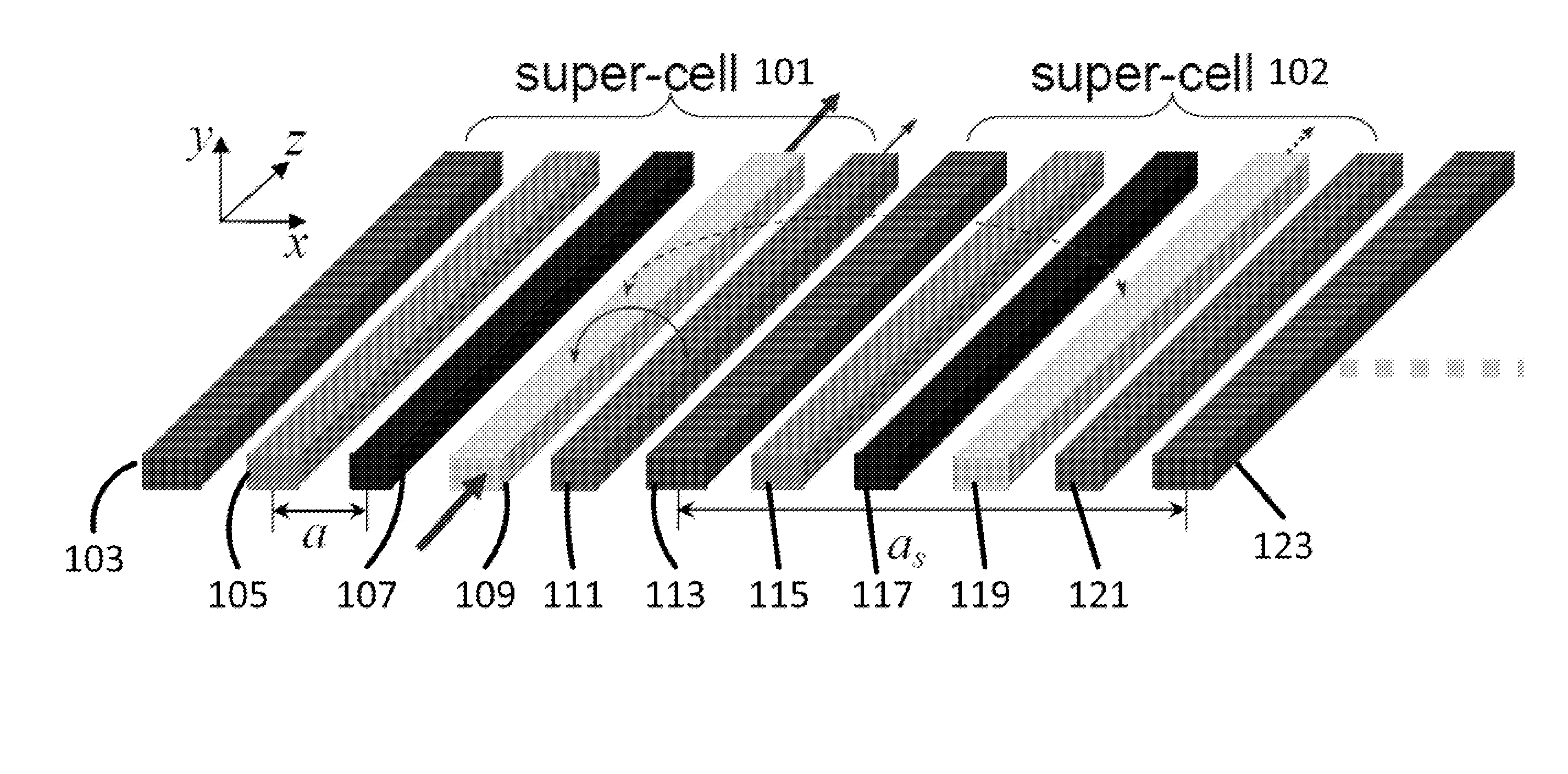
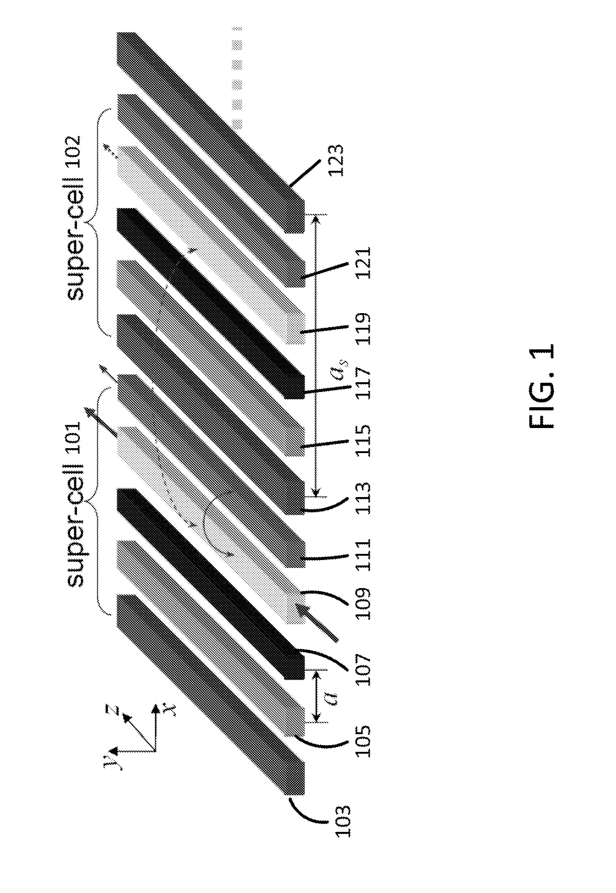
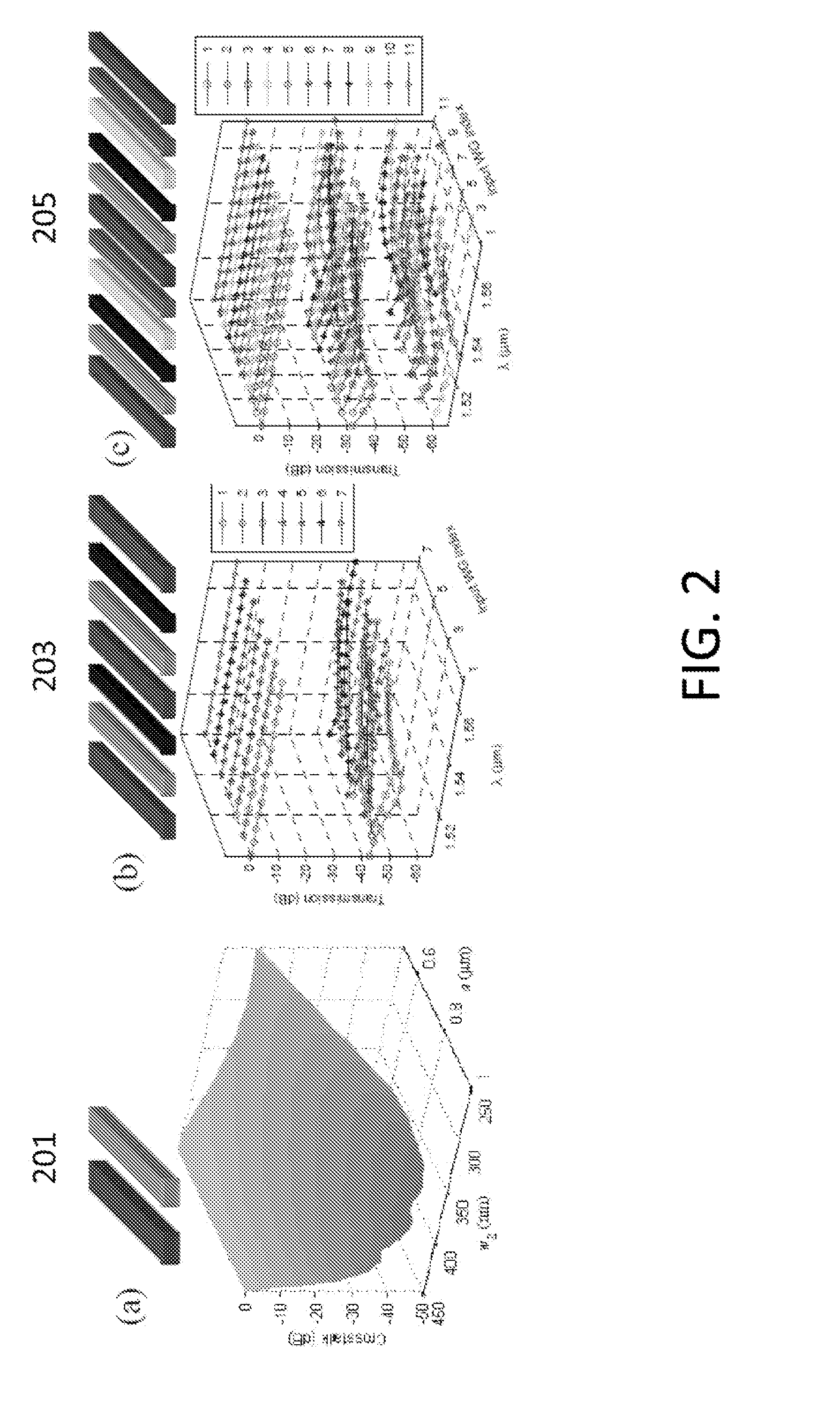
CROSS REFERENCE TO RELATED APPLICATIONS[0001]The present application claims the benefit of U.S. Provisional Application Ser. No. 61 / 877,052 filed on Sep. 12, 2013, the contents of which are hereby incorporated by reference in its entirety.BACKGROUND OF THE INVENTION[0002]Silicon photonics can potentially offer low-cost large-scale integration for photonics technology. Integration density is a key factor for its integration potential and economy of scale. Existing silicon photonics technology has not achieved integration density of one waveguide per micron. Although there exist approaches to high-density photonics integration at the expense of other performance metrics (e.g., Optical loss and / or crosstalk), a solution to high density photonics integration with minimal impact on other aspects of performance remain a central problem in practical photonic systems. Crosstalk between adjacent waveguiding components sets a fundamental limit for integration density. As the waveguide spacing...

Claims


Application Information

Patent Timeline
IPC IPC(8): G02B6/122G02B6/293G02B6/10
CPCG02B6/122G02B6/2938G02B6/107
Inventor JIANG, WEI
Owner RUTGERS THE STATE UNIV
Learn More