Navigation system and method for dental and cranio-maxillofacial surgery, positioning tool and method of positioning a marker member

a navigation system and craniomaxillofacial technology, applied in boring tools, dental prosthetics, dental tools, etc., can solve the problems of insatiable ergonomic situation of surgeons, limited use of drilling templates, and limited overall precision of drilling templates, etc., to achieve precise surgical navigation and simple and reliable manner

Active Publication Date: 2016-08-18
MININAVIDENT
View PDF30 Cites 14 Cited by
  • Summary
  • Abstract
  • Description
  • Claims
  • Application Information

AI Technical Summary

Benefits of technology

[0093]The method of positioning the marker member of the invention is a method of using the positioning tool of the invention. Hence, the further features disclosed in connection with the above description of the positioning tool of the invention may also be applied to the positioning method of the invention.
[0094]The invention further provides a navigation method for dental and cranio-maxillofacial surgery using the navigation system of the invention. The navigation method comprises the steps of imaging at least part of the area in which surgery is performed by means of the imaging unit, determining whether the plurality of marker elements are detected by the imaging unit, and, if it is determined that the plurality of marker elements are not detected by the imaging unit, moving the imaging unit relative to the surgical handpiece or instrument to a position in which the imaging unit detects the plurality of marker elements.
[0095]The navigation method of the invention provides the advantageous effects already described in detail above for the navigation system of the invention. In particular, the navigation method enables precise surgical navigation during dental and cranio-maxillofacial surgery in a simple and reliable manner. The method allows for the relative position between the surgical handpiece or instrument and the marker member to be precisely determined in a simple and reliable way.
[0096]The navigation method may further comprise the step of locking or arresting the imaging unit in one or more positions relative to the surgical handpiece.
[0097]The navigation method may further comprise the step of detecting or sensing the position of the imaging unit relative to the surgical handpiece.
[0098]The navigation method may comprise the step of sliding, pivoting or rotating the imaging unit relative to the surgical handpiece, e.g., to a position in which the imaging unit detects the plurality of marker elements.

Problems solved by technology

The use of such drilling templates is still limited because the production thereof is complex, time-consuming (about 3 to 10 days) and expensive (about 300 to 700 FUR per template).
Moreover, the overall precision with drilling templates is limited to approximately 1 to 2 mm and the ergonomic situation for the surgeon is not satisfactory, due to the problem of a blocked view during surgery.
However, the use of the tracking system and the two reference assemblies renders the above device complex.
Further, the requirement of the two reference assemblies constantly being located within the field of vision of the stationary tracking system imposes limitations on the applicability of the device.
Specifically, in dental and cranio-maxillofacial surgery, in particular, in intraoral applications, in which the area to be treated is arranged within the patient's oral cavity, this requirement may be difficult or even impossible to fulfil, at least throughout the entire surgical procedure.

Method used


Image

  • Navigation system and method for dental and cranio-maxillofacial surgery, positioning tool and method of positioning a marker member
  • Navigation system and method for dental and cranio-maxillofacial surgery, positioning tool and method of positioning a marker member
  • Navigation system and method for dental and cranio-maxillofacial surgery, positioning tool and method of positioning a marker member

Examples


Embodiment Construction

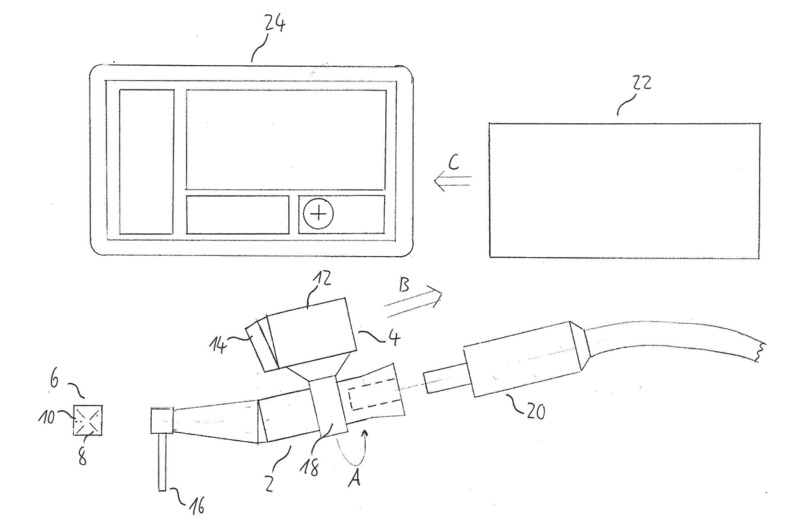
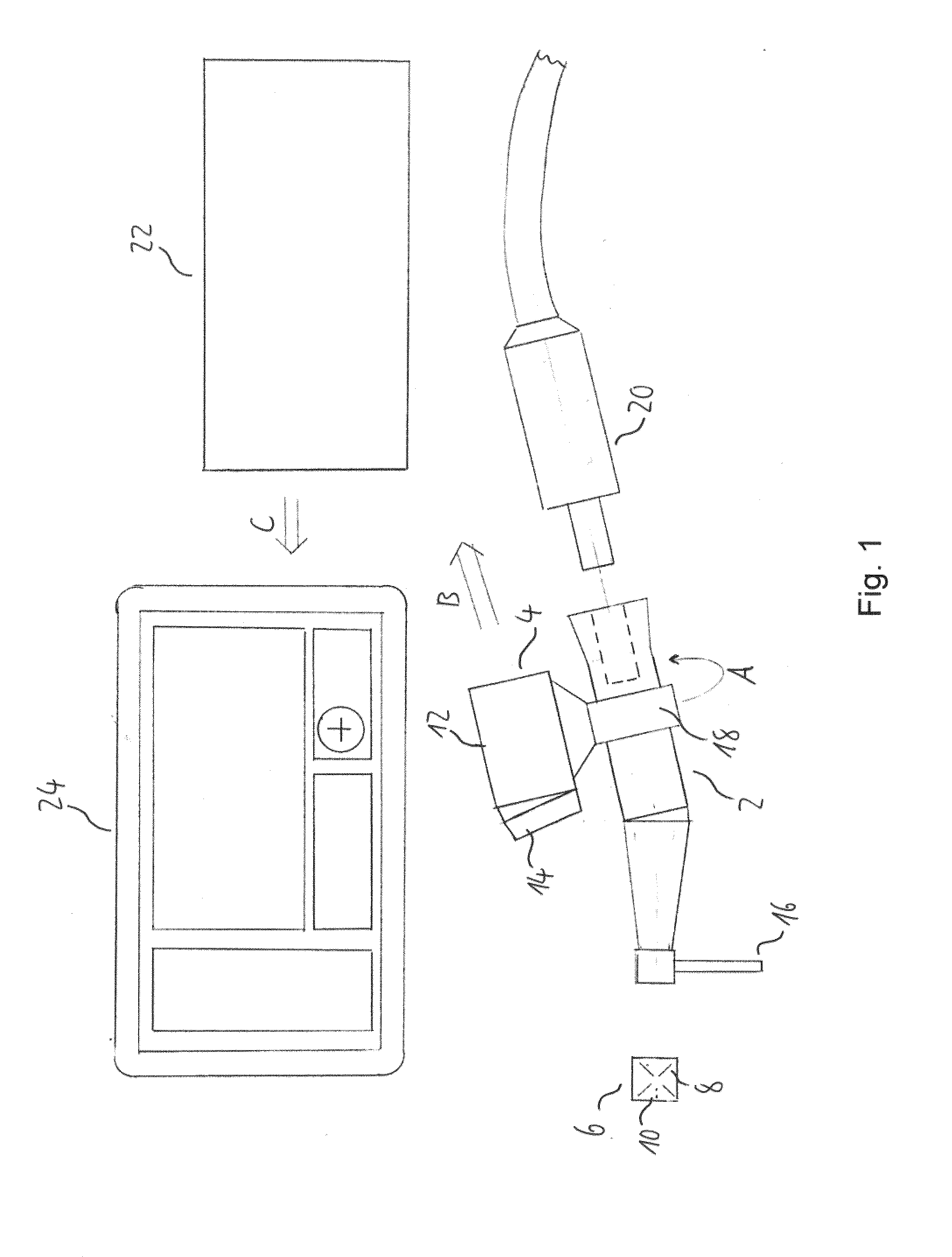
[0110]FIG. 1 shows a schematic side view of a navigation system for dental and cranio-maxillofacial surgery according to a currently preferred embodiment of the present invention.

[0111]The navigation system comprises a surgical handpiece, namely a dental drill 2, an imaging unit 4 which is movably attached to the drill 2 and a marker member 6 which is attachable to a cranial bone, a facial bone, a tooth or teeth of a patient. The marker member 6 comprises a plurality of marker elements, namely reference lines 8 and reference points 10, which are detectable by the imaging unit 4.

[0112]The reference lines 8 and the reference points 10 are printed onto a surface of a body of the marker member 6 and arranged in a two-dimensional optical pattern. The body of the marker member 6 is made of a rigid material, such as hard plastic, metal, ceramic or the like. The marker member 6 further comprises an attachment element (not shown), such as a screw element, a clamp element, an adhesive element...


PUM


Abstract

The invention relates to a navigation system for dental and cranio-maxillofacial surgery, comprising a surgical handpiece (2), an imaging unit (4) which is movably attached to the surgical handpiece (2), and a marker member (6; 44, 46) which is attachable to a cranial bone, a facial bone (26), a tooth or teeth of a patient. The marker member (6; 44, 46) comprises a plurality of marker elements (8, 10; 46) which are detectable by the imaging unit (4). Further, the invention relates to a positioning tool (40) for use with the navigation system, wherein the positioning tool (40) is configured for positioning the marker member (44, 46) on a patient's cranial bone, facial bone (26), tooth or teeth and comprises a die element (42) and the marker member (44, 46). The marker member (44, 46) comprises a deformable material (44), the deformable material (44) is releasably received in the die element (42) and the plurality of marker elements (46) are arranged on a surface of the deformable material (44) which faces the die element (42), The invention further relates to a navigation method for dental and craniomaxillofacial surgery using the navigation system and to a method of positioning a marker member (44, 46) on a patient's cranial bone, facial bone (26), tooth or teeth using the positioning tool (40).

Description

FIELD OF THE INVENTION[0001]The invention relates to a navigation system for dental and cranio-maxillofacial surgery comprising a marker member and to a navigation method using this navigation system. Further, the invention relates to a positioning tool for use with the navigation system and to a method of positioning the marker member of the navigation system on a patient's tooth or teeth.BACKGROUND ART[0002]About 5 million dental implant procedures were carried out in Europe in 2012. Approximately 18% of these procedures were performed with the use of treatment planning software and approximately 4% of these procedures used mechanical drilling templates as tool for guided surgery.[0003]The use of such drilling templates is still limited because the production thereof is complex, time-consuming (about 3 to 10 days) and expensive (about 300 to 700 FUR per template). Moreover, the overall precision with drilling templates is limited to approximately 1 to 2 mm and the ergonomic situat...

Claims


Application Information

Patent Timeline
Patent Type & Authority Applications(United States)
IPC IPC(8): A61B34/20A61C8/00A61B1/00A61B34/10A61B1/24A61B6/14
CPCA61C3/02A61B34/20A61B2017/00946A61C1/084A61C1/12A61B2090/3983A61B2090/373A61B2034/2055A61B2034/2057A61B2090/3995A61C8/0089A61B2090/3916A61B2034/2072A61B34/10A61B6/14A61B1/24A61B1/00045A61B2090/309A61B2090/0811A61B2034/107A61B2090/371A61B2034/2065A61B2090/3937A61B2090/3966A61B2090/3987A61C9/0053
Inventor ZEILHOFER, HANS-FLORIANJURGENS, PHILIPPSCHKOMMODAU, ERIKBERLINGHOFF, FRANK
Owner MININAVIDENT
Why Eureka
Try Eureka