Toothed sprocket with elastic centering element

a technology of elastic centering element and sprocket, which is applied in the direction of couplings, hoisting equipment, transportation and packaging, etc., can solve the problems of low production cost of mass products, low quality fit manufacturing, and wiggle between the two components

Active Publication Date: 2016-08-18
THE GATES CORP
View PDF0 Cites 7 Cited by
  • Summary
  • Abstract
  • Description
  • Claims
  • Application Information

AI Technical Summary

Benefits of technology

[0011]The invention comprises a toothed sprocket hub with elastic centering element comprising an input shaft having a receiving portion and a cylindrical outer surface, a sprocket engagable with the input shaft, the sprocket comprising at least two first surfaces each disposed on a bending beam such that each first surface is elastically moveable in a radial direction, the two first surfaces bearing upon the outer surface, the two first surfaces each having a radius d that is less than a radius D of the outer surface, at least one second surface that is radially moveable to a lesser extent than a first surface, the second surface engaging the receiving portion to prevent a relative rotation of the sprocket with the input shaft, and a third surface in cooperative relation to the second surface, the third surface bearing upon the outer surface of the input shaft, the third surface having a clearance fit with the outer surface.

Problems solved by technology

However, under load and if tolerances between the shaft and hub are too large, it can lead to wobbling between the two components.
On the other hand high-quality fits are relatively expensive to manufacture using machining processes.
This is a disadvantage when one has to manufacture low-cost mass products.
Because a functioning toothed belt drive requires a defined preload on the belt, a wobbling toothed belt disk on the rear hub would not be able to maintain a constant tension.
The consequence can be squeaking and creaking noises.
This is the problem of deficient centering when using a toothed sprocket with a spline shaft profile in combination with inexpensively available hub gears.

Method used


Image

  • Toothed sprocket with elastic centering element
  • Toothed sprocket with elastic centering element
  • Toothed sprocket with elastic centering element

Examples


Embodiment Construction

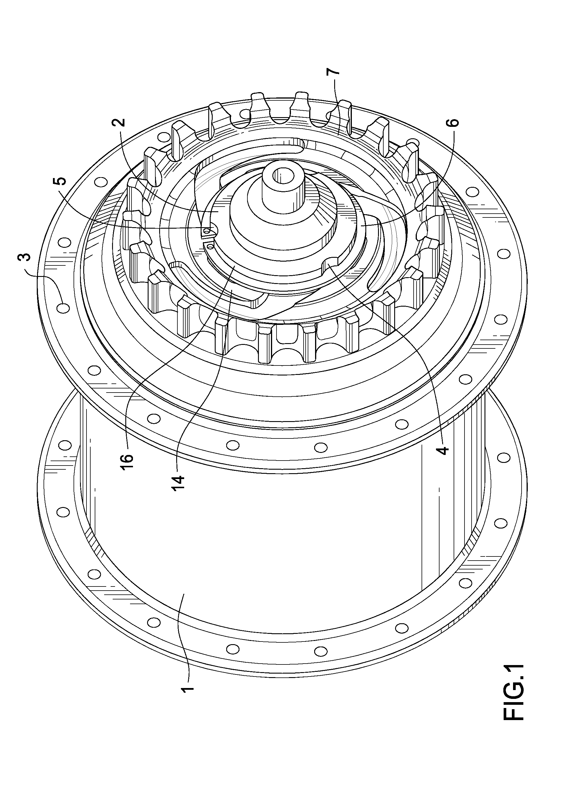
[0018]FIG. 1 shows a rear hub 1 of a bicycle without spokes or rim. Torque is transmitted to a toothed belt drive via a foot pedal or crank (not shown). The toothed belt transfers torques to the toothed sprocket 7, which in turn drives the input shaft 2.

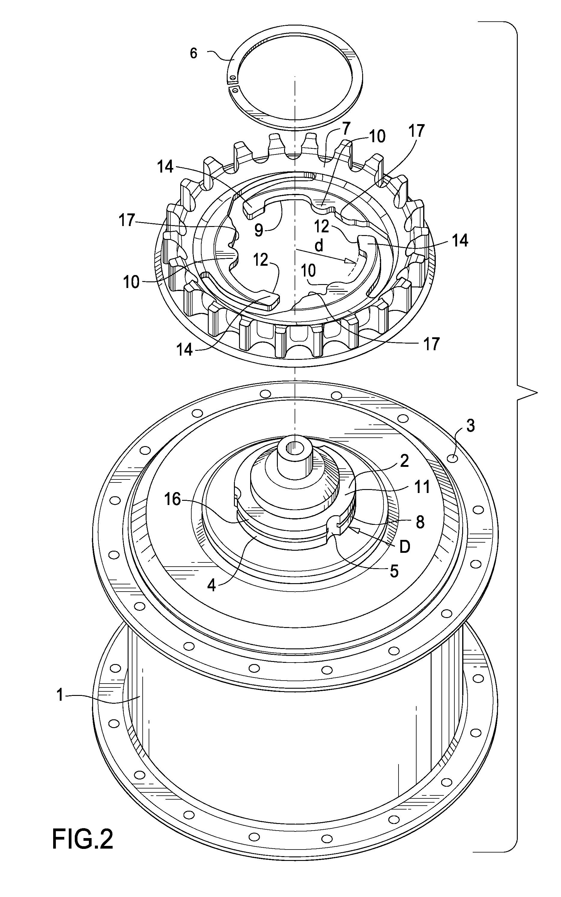
[0019]This arrangement transmits torque via a shaft / hub connection 4 into the hub input shaft. A bicycle rim with tire (not shown) is driven by the rear hub 1 via spokes that are mounted inside the spoke holes 3. This is a known structure on a bicycle wheel. Toothed sprocket 7 is held axially on the input shaft 2 via a snap ring 6.

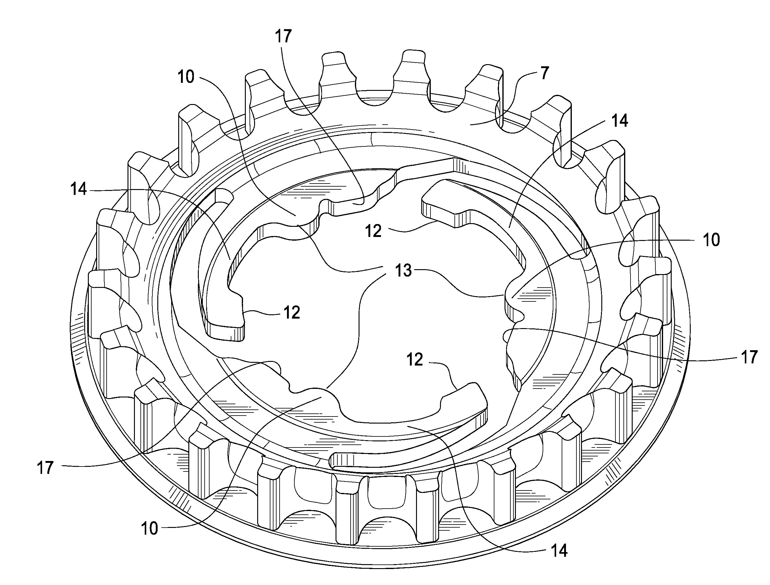
[0020]Sprocket 7 transmits torque via three receiving portions or grooves 5 which are engaged by projections 10. Cylinder-shaped outer surface 16 provides for correct centering of the toothed sprocket 7 on the input shaft 2. However, correct centering is only possible if the bore 9 of toothed sprocket 7 is seated without play in relation to the cylinder-shaped lateral surface 16. This is achieved in the rad...


PUM


Abstract

A toothed sprocket hub with elastic centering element comprising an input shaft having a receiving portion and a cylindrical outer surface, a sprocket engagable with the input shaft, the sprocket comprising at least two first surfaces each disposed on a bending beam such that each first surface is elastically moveable in a radial direction, the two first surfaces bearing upon the outer surface, the two first surfaces each having a radius d that is less than a radius D of the outer surface, at least one second surface that is radially moveable to a lesser extent than a first surface, the second surface engaging the receiving portion to prevent a relative rotation of the sprocket with the input shaft, and a third surface in cooperative relation to the second surface, the third surface bearing upon the outer surface of the input shaft, the third surface having a clearance fit with the outer surface.

Description

FIELD OF THE INVENTION[0001]The invention relates to a toothed sprocket, and more particularly to a toothed sprocket with elastic centering element having a first surface disposed on a bending beam and radially moveable, a second surface radially moveable to a lesser extent that the first surface, and a third surface in cooperative relation to a second surface, the third surface bearing upon the outer surface of the input shaft, the third surface having a clearance fit with the outer surface.BACKGROUND OF THE INVENTION[0002]Chain drives are the predominant means of power transmission on two-wheelers such as bicycles. Chains are also used for power transmission on numerous machines. Very often, the chain sprockets are connected to a shaft via a form-fitting shaft / hub connection. In general, these and other connections work with local elevations and depressions with respect to a cylinder-shaped connection surface. Some free play fit between the shaft and hub is important for the prope...

Claims


Application Information

Patent Timeline
Patent Type & Authority Applications(United States)
IPC IPC(8): B62M9/02F16H55/30
CPCB62M9/02F16H2055/306F16D1/112F16D1/116B60B27/023F16H57/0025F16H55/171B60B27/04F16H55/30F16D3/62
Inventor CODY, MICHAEL
Owner THE GATES CORP
Why Eureka
Try Eureka