Circuit Arrangement for Cable Checking, Cable Testing, Cable Diagnosis and/or Cable Fault Localization and Device with a Circuit Arrangement of that Type

a circuit arrangement and cable testing technology, applied in the direction of measuring devices, testing dielectric strength, instruments, etc., can solve the problems of affecting the accuracy of measurement process, and not being able to influence the design of high-voltage testing devices. , to achieve the effect of simple and potential-free manner

Active Publication Date: 2016-08-18
MEGGER GERMANY GMBH
View PDF2 Cites 18 Cited by
  • Summary
  • Abstract
  • Description
  • Claims
  • Application Information

AI Technical Summary

Benefits of technology

[0029]The two low ends of the voltage multipliers that are connected to one another are connected to the low end of the test specimen as the load impedance via the measurement impedance that is adaptable to the measuring range for precise recording of the measured values. The low ends of the high-voltage cascades are therefore connected to the auxiliary ground. The direction of the current can be measured with the auxiliary ground. A high-resolution and precise measurement of the loss factor (tan delta) of the cable is therefore possible.
[0036]According to another design form, the main converters are connected with one another in such a way that the switches of the main converter switch with a synchronous frequency or with a synchronous frequency with phase-shifted switching points to reduce or eliminate beat effects and electrical interference.
[0050]The power for the control circuit of the current source is obtained from the current that flows through the current source itself. A problematic, inductive, auxiliary power transmission process that would otherwise exist can therefore be eliminated. The signal transmission for the control takes place in a simple and potential-free manner through a fiber-optic cable. The fiber-optic cable simultaneously offers a very favorable and simple possibility to provide insulation between a grounded regulator of the current sources and the controls of the current sources, for instance in a high-voltage testing device.
[0054]the insulation is easy to realize with very high voltages and frequencies and
[0058]The high-voltage measuring divider distinguishes itself, in particular, by very strong independence from parasitical elements.

Problems solved by technology

This regulatory intervention leads to corners in the progression of the test voltage, which in turn cause harmonic waves and noise.
There is a negative influence on the precision of the measurement process because of that.
It cannot be influenced by a suitable design of the high-voltage testing device.

Method used


Image

  • Circuit Arrangement for Cable Checking, Cable Testing, Cable Diagnosis and/or Cable Fault Localization and Device with a Circuit Arrangement of that Type
  • Circuit Arrangement for Cable Checking, Cable Testing, Cable Diagnosis and/or Cable Fault Localization and Device with a Circuit Arrangement of that Type
  • Circuit Arrangement for Cable Checking, Cable Testing, Cable Diagnosis and/or Cable Fault Localization and Device with a Circuit Arrangement of that Type

Examples


first embodiment

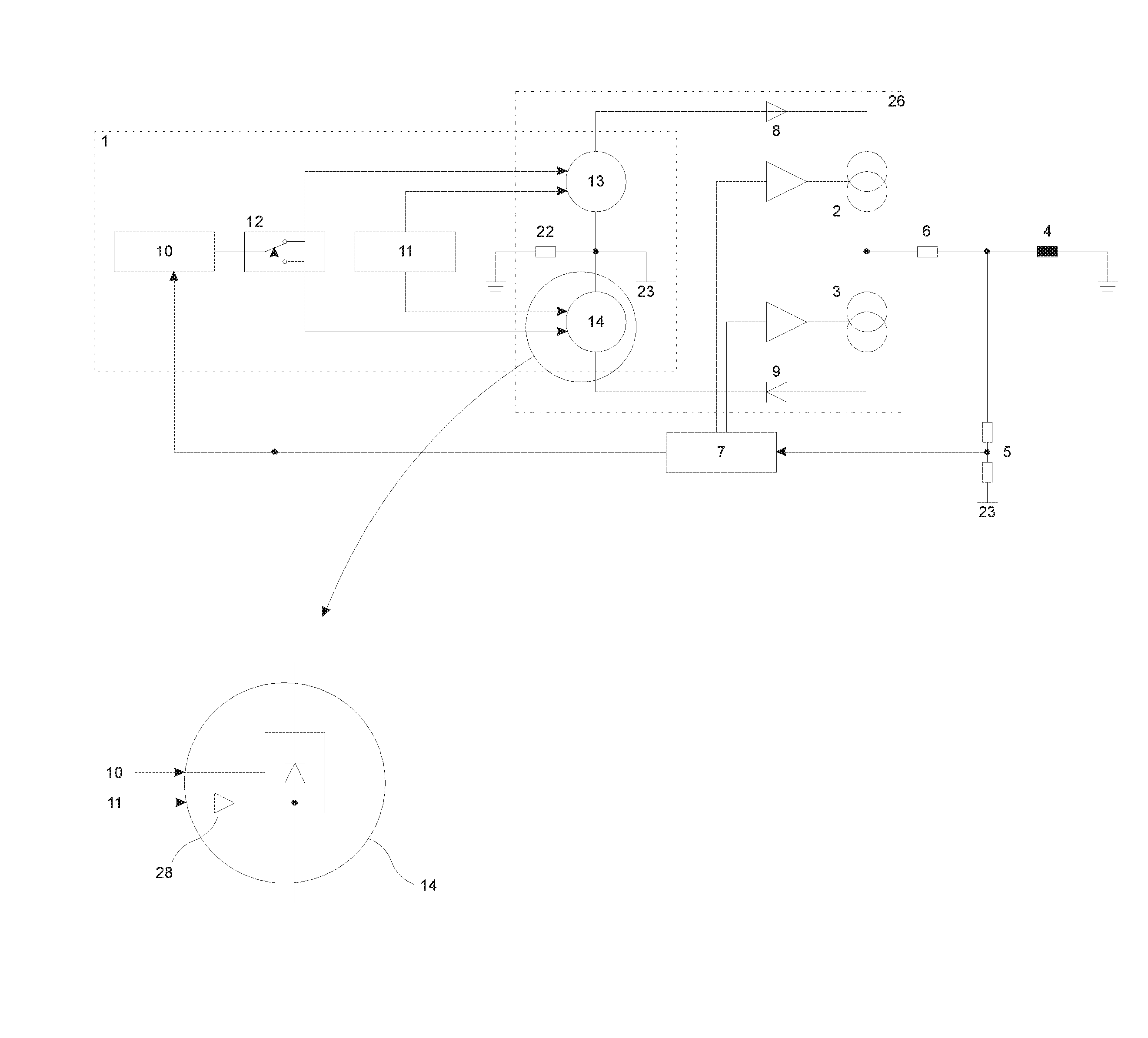
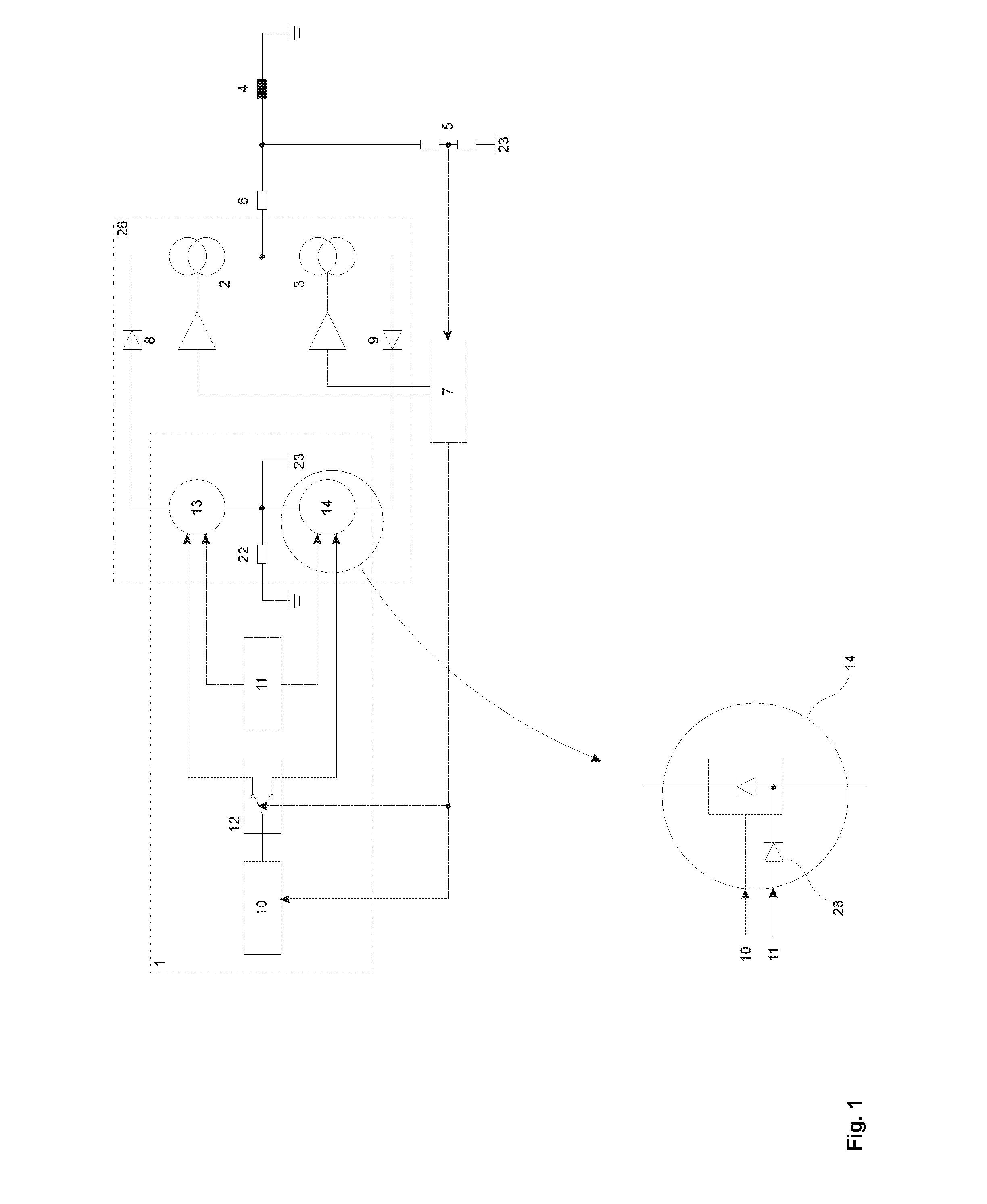
[0090]In the example, the voltage source 1 has a main converter 10, an auxiliary converter 11, a switching arrangement 12 and a first voltage multiplier 13 for a positive voltage and a second voltage multiplier 14 for a negative voltage. FIG. 1 shows a circuit arrangement for cable checking, cable testing, cable diagnosis and / or cable fault localization with a main converter 10 and an auxiliary converter 11 in a basic diagram.

[0091]The first voltage multiplier 13 for a positive voltage and the second voltage multiplier 14 for a negative voltage of the voltage source 1 are interconnected via the coupling diodes 8, 9 to the current sources 2, 3 that are connected to one another, forming an intermediate circuit 26 with an intermediate-circuit voltage. The coupling diodes 8, 9 prevent back-feed from the voltage multipliers 13, 14.

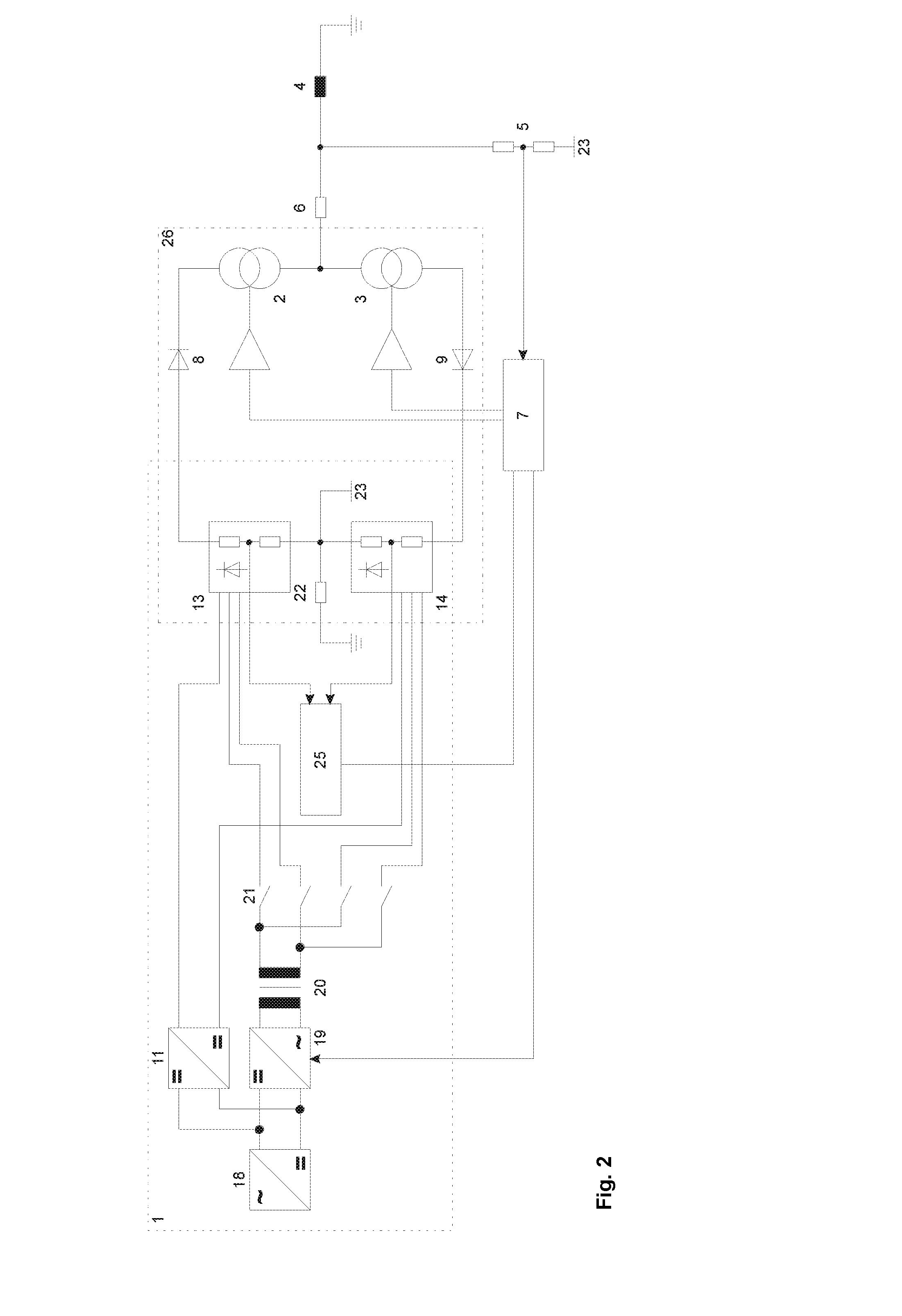
[0092]FIG. 2 shows a circuit arrangement for cable checking, cable testing, cable diagnosis and / or cable fault localization with a concrete realization of the ...

second embodiment

[0123]In the example, the voltage source 1 has a first main converter 10a, a second main converter 10b, a switching arrangement 12 and the first voltage multiplier 13 for a positive voltage and the second voltage multiplier 14 for a negative voltage.

[0124]FIG. 6 shows a circuit arrangement for cable checking, cable testing, cable diagnosis and / or cable fault localization with two main converters 10a, 10b in a basic diagram. The main converters 10a, 10b correspond in terms of their function in each case to the main converter 10 of the first embodiment of the example.

[0125]The voltage multipliers 13, 14 are connected to the main converters 10a, 10b in such a way that either a positive voltage of the main converter 10a corresponding to the target-value specification and a constant, unregulated negative voltage of the main converter 10b, or a negative voltage of the main converter 10b corresponding to the target-value specification and a constant, unregulated positive voltage of the mai...

third embodiment

[0156]In the potential-free, voltage-controlled current source, the inverting input of the operational amplifier 32 is connected via an inverting amplifier 36, as a further component of the control circuit 29, to the low end 35 of the current source. The connection of the resistor R and the zener diode ZD is the reference potential 37 of the control circuit 29, so the current for supplying the control circuit 29 is routed through the resistor R. The current for supplying the control circuit 29 is therefore a component of the specified target value. The output of the operational amplifier 32 is connected through the level adapter 33 and a device 38 for monitoring the current in the gate resistances RG1, RG2 . . . RGN of the transistors T1, T2 . . . TN and therefore the gate-voltage balancing system. This device 38, as a further component of the control circuit 29, is connected to the demodulator 31, so a back-connection exists to the lead-in voltage of the current source.

[0157]A supp...


PUM


Abstract

The invention relates to circuit arrangements for cable checking, cable testing, cable diagnosis and / or cable fault localization witha voltage source having a first voltage multiplier for a positive voltage and a second voltage multiplier for a negative voltagecurrent sources that are connected to one another in combination with the voltage multipliers to generate a test voltage over the load impedance of the cable to charge and discharge the load capacitance of the cable anda control device that is interconnected with the voltage source and the current sources anddevices with a circuit arrangement of that type.The circuit arrangements distinguish themselves, in particular, by the fact that arbitrary voltage curves of different amplitudes can be generated through the cable as the impedance acting as the test specimen.

Description

CROSS REFERENCE TO RELATED APPLICATIONS[0001]This application claims the priority of German Application No. DE 102015202597.7 filed on Feb. 12, 2015; this application is incorporated by reference herein in its entirety.BACKGROUND[0002]The invention relates to circuit arrangements for cable checking, cable testing, cable diagnosis and / or cable fault localization with[0003]a voltage source having a first voltage multiplier for a positive voltage and a second voltage multiplier for a negative voltage[0004]current sources that are connected to one another in combination with the voltage multipliers to generate a test voltage over the load impedance of the cable to charge and discharge the load capacitance of the cable and[0005]a control device that is interconnected with the voltage source and the current sources and devices with a circuit arrangement of that type.[0006]A method of checking the insulation of electrical operating equipment and a circuit arrangement for carrying out the m...

Claims


Application Information

Patent Timeline
Patent Type & Authority Applications(United States)
IPC IPC(8): G01R31/02
CPCG01R31/021G01R31/14G01R31/1272G01R27/2694G01R31/58
Inventor STECHEMESSER, NICO
Owner MEGGER GERMANY GMBH
Why Eureka
Try Eureka