Electrical impedance tomography system

a tomography system and impedance technology, applied in the field of electric impedance tomography system, can solve the problems of low spatial resolution of images or heat maps, unclear anatomic structure, and difficulty in interpretation of eit-images, and achieve the effects of saving time and resources, improving image interpretation and correlation with anatomy, and saving time and resources

Active Publication Date: 2016-08-25
SWISSTOM
View PDF10 Cites 20 Cited by
  • Summary
  • Abstract
  • Description
  • Claims
  • Application Information

AI Technical Summary

Benefits of technology

[0032]It is an advantage of the present invention to advance EIT to a standardized and reliable diagnosis instrument, which provides reproducible, comparable and reliable results.
[0033]It is a further advantage of the present invention to provide an EIT system in which image interpretation and correlation with anatomy is improved. It is an advantage of present invention to provide an economical, time and resource saving solution.
[0034]It is an advantage of the present invention to overcome or alleviate the above-discussed drawbacks of prior art.SUMMARY OF THE INVENTION
[0035]Said advantages are accomplished by providing an electrical impedance tomography (EIT) system for determining electric properties of an internal body section of a patient (11) comprising
[0036]an electrode array (13) locatable in electrical contact with the body, such as an external surface, of a patient (11);
[0037]device (15) for applying an electrical current or voltage between two or more electrodes of the electrode array (13) and for measuring generated electrical voltages and / or currents between other pair combinations of the electrode array (13);

Problems solved by technology

Although this technique provides images which represent the distribution of electrical properties within the body, sometimes referred to as heat-maps, in general these images or heat maps have low spatial resolution and the correlation with the actual anatomic structure is unclear.
Therefore, EIT-images are usually difficult to interpret.
Correctly speaking, Electrical Impedance Tomography (EIT) does not provide an image of impedance distribution.
Consequently, objective and standardized EIT images are hard to come by.
Pathological conditions of different patients detected by means of EIT may be hard to detect and cannot be compared readily.
Despite the grid aid, comparison of the CT and EIT images is difficult due to the differences in the shape of the seemingly corresponding regions of interest in the CT and the EIT images.
Moreover, visual comparison aided by this grid reveals obvious discrepancies in the grid position between CT and EIT images.
Despite the grid aid, accuracy of the contrasting juxtaposition is not satisfactory.
A circular or even oval frame into which most commonly the EIT images are projected by an EIT reconstruction algorithm does not produce images which correspond accurately to the anatomy, and is therefore difficult to compare with anatomically accurate images such as from CT or MRI.
A drawback of any one of above mentioned systems and methods is the lack of a system-intrinsic positioning tool, which allows to align the EIT image with a true reference point or patient anatomy.
Moreover, as soon as a test person moves before or during the EIT measurement, the superposed or juxtaposed image will not show the correct reference in any case.
However, in practice, the first and foremost problem of this method is that a 3D model needs to be created from a particular patient's anatomical imaging.
Therefore, this is an expensive, time consuming, laborious method which may even involve specific risks such as radiation or the intrahospital transport of mechanically ventilated ICU patients.
Moreover, the models being extruded shapes are not realistic approximations to the true three-dimensional shape of the thorax.
The impedance images achieved with this method are similar to or even identical with those created by traditional electrical impedance images with their known limitations such as a lack of anatomical accuracy.

Method used


Image

  • Electrical impedance tomography system
  • Electrical impedance tomography system
  • Electrical impedance tomography system

Examples


example

[0183]EIT data measurement and evaluation on a particular patient comprising the steps of:

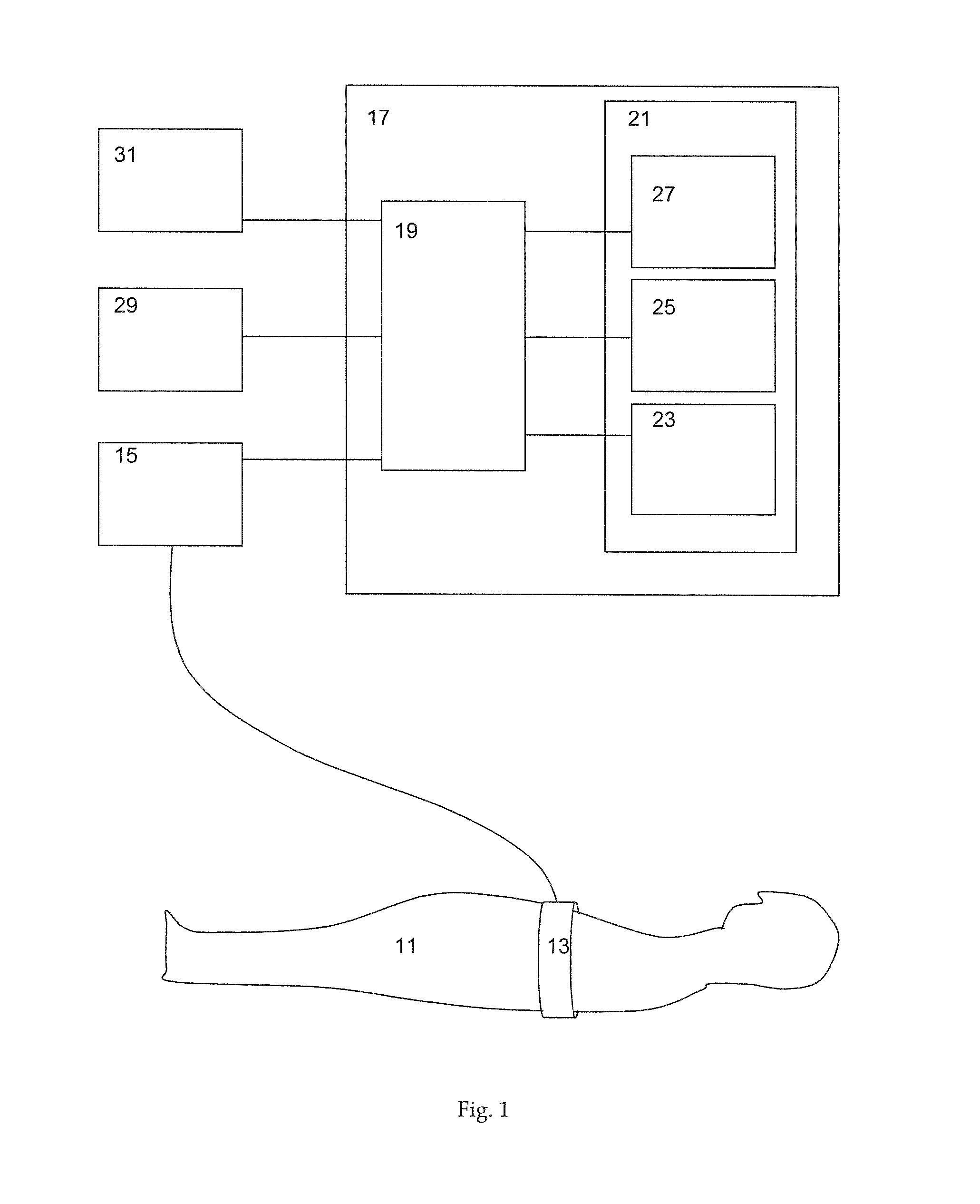
[0184]For a particular patient one of the patient-category-specific models (which is e.g. stored in storage such as reference numeral 25 of FIG. 1) is selected based on the patient's body height, body weight and optionally the gender (which were e.g. entered via an input interface such as reference numeral 29 of FIG. 1).

[0185]EIT and gravity vector data of the patient are measured (e.g., simultaneously).

[0186]The selected 3D anatomical model is used in reconstructing the EIT image from the measured voltages, here specifically for calculation of a patient-category specific reconstruction matrix.

[0187]The 2D organ contour is associated with the selected patient-category-specific 3D anatomical model for display on a graphical user interface (GUI). The display on the GUI serves as a reference platform for the reconstructed EIT image, in that the selected patient-category-specific contour and the pa...


PUM


Abstract

An electrical impedance tomography system for determining electric properties of an internal body part of a patient comprises an electrode array in electrical contact with the patient, a device for applying current or voltage between electrodes of the array and for measuring voltages or currents between other combinations of the array. A computing unit comprises a processor and a storage unit. The storage unit comprises a reconstruction algorithm used by the data processor for reconstructing the measured voltages of the body part into electrical properties or changes thereof. The data processor outputs a representation of the reconstructed electrical properties and generates or processes anatomical models descriptive of the body part. The data processor uses biometric data of the patient and, according to the biometric data of the patient, selects an anatomical model for reconstructing the measured electrical voltages of the body part into electrical properties or changes thereof.

Description

CROSS-REFERENCE TO RELATED APPLICATIONS[0001]This application is a national phase entry under 35 U.S.C. §371 of PCT / CH2014 / 000143 filed on Oct. 3, 2014, which claims priority to Swiss Patent Application 1710 / 13 filed on Oct. 4, 2013, the entirety of each of which is incorporated by this reference.TECHNICAL FIELD OF THE INVENTION[0002]This invention relates to an electrical impedance tomography system according to the preamble of claim 1.BACKGROUND OF THE INVENTION[0003]Electrical impedance tomography (EIT) is a non-invasive imaging technique based on the injection of current and measurement of voltage through electrodes attached to the body and providing information on the internal body structures. Although this technique provides images which represent the distribution of electrical properties within the body, sometimes referred to as heat-maps, in general these images or heat maps have low spatial resolution and the correlation with the actual anatomic structure is unclear. Theref...

Claims


Application Information

Patent Timeline
Patent Type & Authority Applications(United States)
IPC IPC(8): A61B5/053A61B5/00A61B5/08
CPCA61B5/0536G09B23/30A61B5/0809A61B5/0531A61B5/0035A61B5/6831
Inventor GRYCHTOL, BARTLOMIEJBRUNNER, JOSEF X.BOHM, STEPHAN
Owner SWISSTOM
Why Eureka
Try Eureka