Subxyphoid epicardial ablation

a subxyphoid and epicardial technology, applied in radiation diagnostic clinical applications, endoscopic cutting instruments, applications, etc., can solve the problems of less control of the amount of tissue dissection by the physician, less invasive treatment, and reduced number of devices that the physician must manipulate in the surgical area. , to achieve the effect of less invasive treatmen

Active Publication Date: 2016-08-25
ATRICURE
View PDF5 Cites 2 Cited by
  • Summary
  • Abstract
  • Description
  • Claims
  • Application Information

AI Technical Summary

Benefits of technology

[0015]Increased tissue contact relative to that which can be achieved with known devices is capable of reversing convective cooling effects effect noted above by evoking a compression of the tissue that shortens the wall thickness (e.g., of the atria), ensuring consistent contact throughout the length of the electrode(s), and increasing the efficiency of thermal conduction from the epicardium to the endocardium. As such a more consistent and reliable lesion is created.
[0019]Expanding the balloon can occur during creating of the lesion to separate an anatomical structure from the heart surface. For example, the phrenic nerve or esophagus can be separated or spaced from target tissue to minimize unintentional damage to such structures. Alternatively, or in combination, the method can include cooling tissue using the dilation device before, during or after creating of the lesion.
[0021]In an additional variation, the method can further include drawing a vacuum in the vacuum source to cause a drop in pressure in both the vacuum lumen and the opening, whereupon placing the opening against the soft tissue creates a seal against the soft tissue to cause the fluid perfusion lumen to drop in pressure resulting in fluid flow from the fluid source through the fluid perfusion lumen across the opening and through the vacuum lumen, where when uncovered the opening prevents the perfusion lumen from reducing in pressure and preventing fluid flow.

Problems solved by technology

Clearly, doing so reduces the number of devices that a physician must manipulate in the surgical area as well as the number of devices that are advanced through the body opening / port / incision.
However, because this dissection relies upon somewhat uncontrollable expansion of the balloon (as the internal balloon pressure increases), the physician typically has less control over the amount of tissue dissection as compared to using a non-expanding structure to physically dissect tissue.
While obturator type devices avoid the problems with somewhat unpredictable dissection via balloon expansion, such devices are still not optimal.
In any event, the balloon dissection or dissection via obturator dilation as described above do not provide the physician with the ability to tease or loosen adjoining tissue for a more controlled dissection of tissue.
Another drawback with conventional devices is their failure to accommodate removal of debris that is generated by the tissue dissection process.
Such debris interferes with visualization through the scope.
Without the ability to irrigate the scope, a physician will be forced to repeatedly remove the scope from the surgical site and body for cleaning.
Removal and cleaning of the scope increases the length and therefore the risk associated with the surgical procedure.
Moreover, apart from the debris, in the obturator-type devices described above, the closed transparent end of the device often causes a distorted view of the working area.
However, the devices and methods have applicability to any region in the body apart from the thoracic cavity.

Method used


Image

  • Subxyphoid epicardial ablation
  • Subxyphoid epicardial ablation
  • Subxyphoid epicardial ablation

Examples


examples

[0172]FIGS. 14A to 14F illustrate radiological images of exemplary procedures for subxyphoid introduction of coagulation devices. FIG. 14A illustrates the inerstion of a guided device into the pericardium over a guidewire 62. The physician performs a pericardiocentesis and inserts a into the pericardial space. Then the physician advances a guidewire through the needle into the pericardial space. A balloon catheter 70 that is advanced over the guidewire is inflated to open the pericardial access site. The physician then retracts the balloon 70 to create a channel allowing for advancement of a coagulation or other treatment device over the guidewire and into the pericardial space.

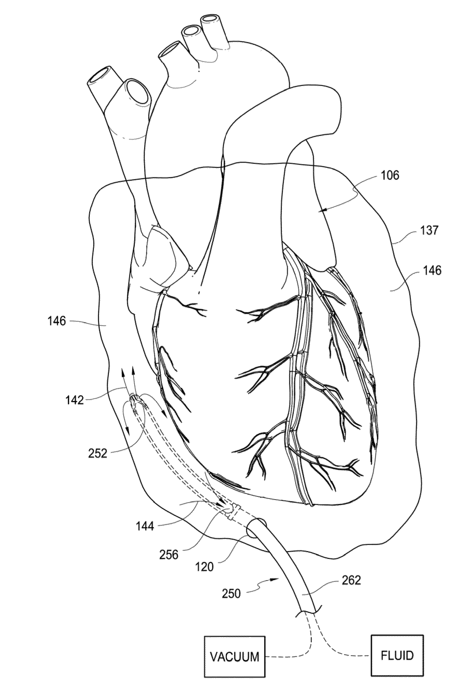
[0173]FIG. 14C shows an example of creation of right atrial lesions. The physician manipulates the treatment device 200 within the pericardium against the right atrium. The physician then positioned the device 200 is over the guidewire and along the right atrium. The devices 200 guidewire lumen (located 1800 ...


PUM


Abstract

Methods and devices described herein facilitate ablation patterns on the heart within a pericardial sac and without opening or deflating the lungs.

Description

RELATED APPLICATIONS[0001]This application is a continuation of U.S. patent application Ser. No. 13 / 107,747 filed, May 13, 2011, which is a non-provisional of U.S. Provisional Applications 61 / 334,499 filed May 13, 2010 and 61 / 334,519 filed May 13, 2010, the entirety of each of which is incorporated by reference herein.BACKGROUND OF THE INVENTION[0002]Methods and devices for access devices to allow improved manipulation of organs and / or instruments within the body by creating working spaces within the body and adjacent to a target site. The methods and devices can be used in various parts of the body. One particular application includes the use of the access devices and methods to advanced devices to a surface of the heart to create atrial lesion patterns one or more atrial surfaces of the heart.[0003]Scope based surgical tools (e.g., elongated cannula / tubular devices that allow viewing of internal body tissues) provide surgeons with an ability to view a surgical site through a lens / ...

Claims


Application Information

Patent Timeline
Patent Type & Authority Applications(United States)
IPC IPC(8): A61B17/00A61B18/14A61F2/958
CPCA61B6/12A61B17/00234A61B18/148A61B18/1492A61B2017/00247A61B2017/003A61B2017/00858A61B2017/320004A61B2017/320012A61B2018/00005A61B2018/00285A61B2018/00291A61B2018/00351A61B2018/00773A61B2018/1435A61B2218/002A61B2218/007A61B2090/065A61B17/32002
Inventor WHAYNE, JAMES G.FLEISCHMAN, SIDNEY D.
Owner ATRICURE
Why Eureka
Try Eureka