
Bubble collector for suction fuel system

Inactive Publication Date: 2016-09-01
SIKORSKY AIRCRAFT
View PDF18 Cites 2 Cited by
  • Summary
  • Abstract
  • Description
  • Claims
  • Application Information

AI Technical Summary

Benefits of technology

The patent describes a fuel feed system for a rotary-winged aircraft that aims to prevent air bubbles from affecting the engine's fuel suction pump. The system includes a collector that captures air-vapor from the fuel as it flows through the line, and an air-vapor line that directs the air-vapor back to the fuel source or out of the engine. This helps to keep the air pumped out of the engine fuel system and ensures the engine runs smoothly.

Problems solved by technology

In a suction type fuel feed system, however, the suction acting on the fuel can cause air and fuel vapor dissolved in the fuel to come out of solution and form bubbles in the fuel as it travels up the fuel line to the engine fuel pump.
The engine fuel pump has a maximum allowable vapor-to-liquid volume fraction (V / L) and a maximum allowable bubble size at the pump's fuel inlet which the pump can tolerate, beyond which, the fuel pump will lose its priming and stop pumping fuel, resulting in engine flame-out.
Engine fuel feed lines are generally designed to limit the fuel line pressure drop such that the calculated V / L ratio at the engine fuel pump inlet, based on the worst case combinations of altitude, fuel type, fuel pressure, fuel temperature, and aircraft g loading, is limited to the level the engine fuel pump can tolerate.
However, constraints on the fuel line sizing and routing imposed by the helicopter configuration can cause occasional or periodic local concentrations of bubbles in the fuel line which are larger than the maximum bubble size that the engine pump can tolerate even when the overall time-averaged V / L ratio determined based on altitude, fuel type, fuel pressure, and fuel temperature is within the engine fuel pump limit.
The diameter and flow area of the fuel line needed to meet the allowable fuel line pressure drop for a given fuel line geometry can result in fuel velocities below the bubble rise velocity, particularly at low fuel flows.
The time in which the V / L is above average corresponds to an above-average bubble size, which, if it is large enough, would cause pump loss of prime and engine flame-out.
Another possible cause of a momentary large amount of air-vapor at the engine fuel pump's fuel inlet is a natural bubble trap in the fuel line which can occur at some aircraft attitudes, but not at others.
If the aircraft operates for a period of time at attitudes in which a large enough volume of air-vapor to cause fuel pump loss of priming is trapped at a local location in the fuel line and then the aircraft changes to an attitude at which the air-vapor is no longer trapped at that location, the large volume of air-vapor would suddenly travel all at once to the engine fuel pump inlet, possibly resulting in engine flame-out.
Engine fuel feed lines with relatively long, near-horizontal sections can cause this situation.
Using a boost pump to pressurize the fuel line, however, negates the safety benefit of the suction system when the boost pump is operating.

Method used


Image

  • Bubble collector for suction fuel system
  • Bubble collector for suction fuel system
  • Bubble collector for suction fuel system

Examples


Embodiment Construction

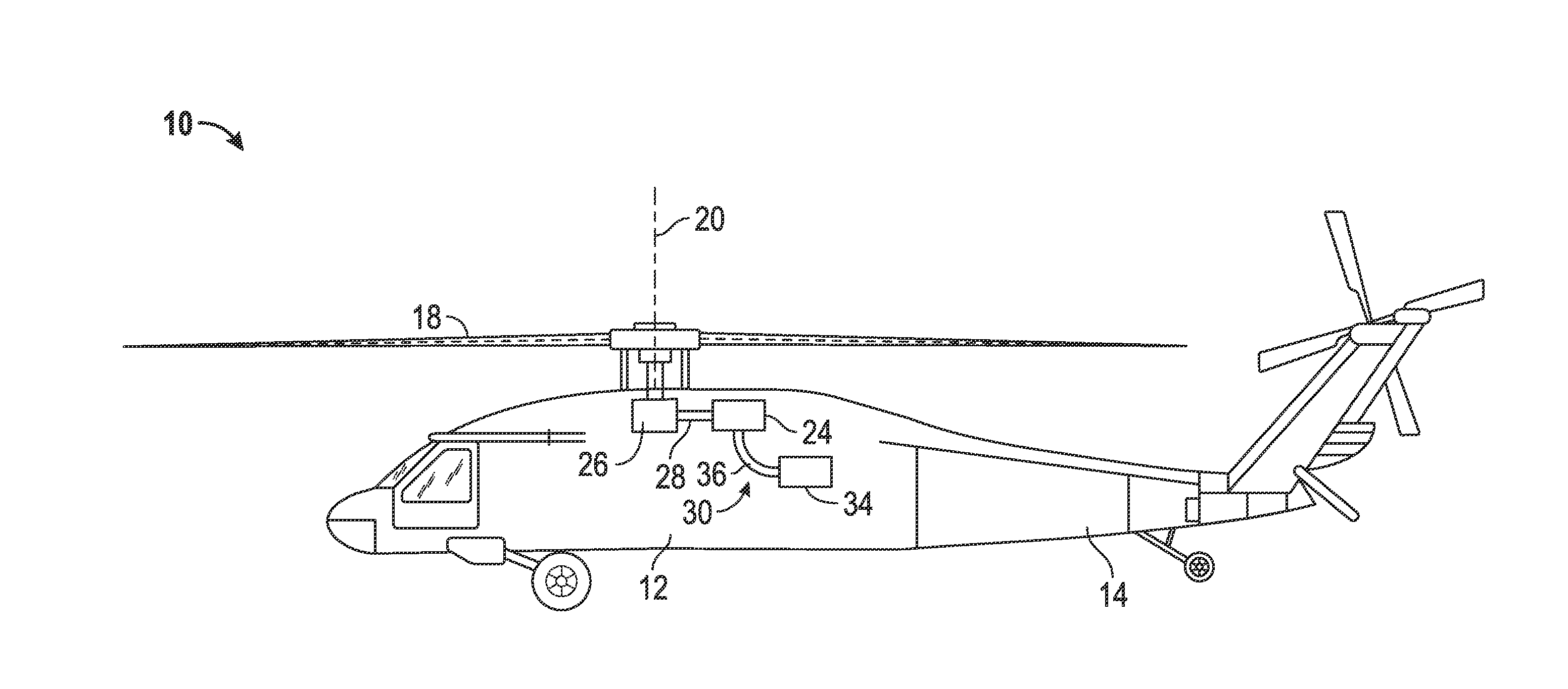
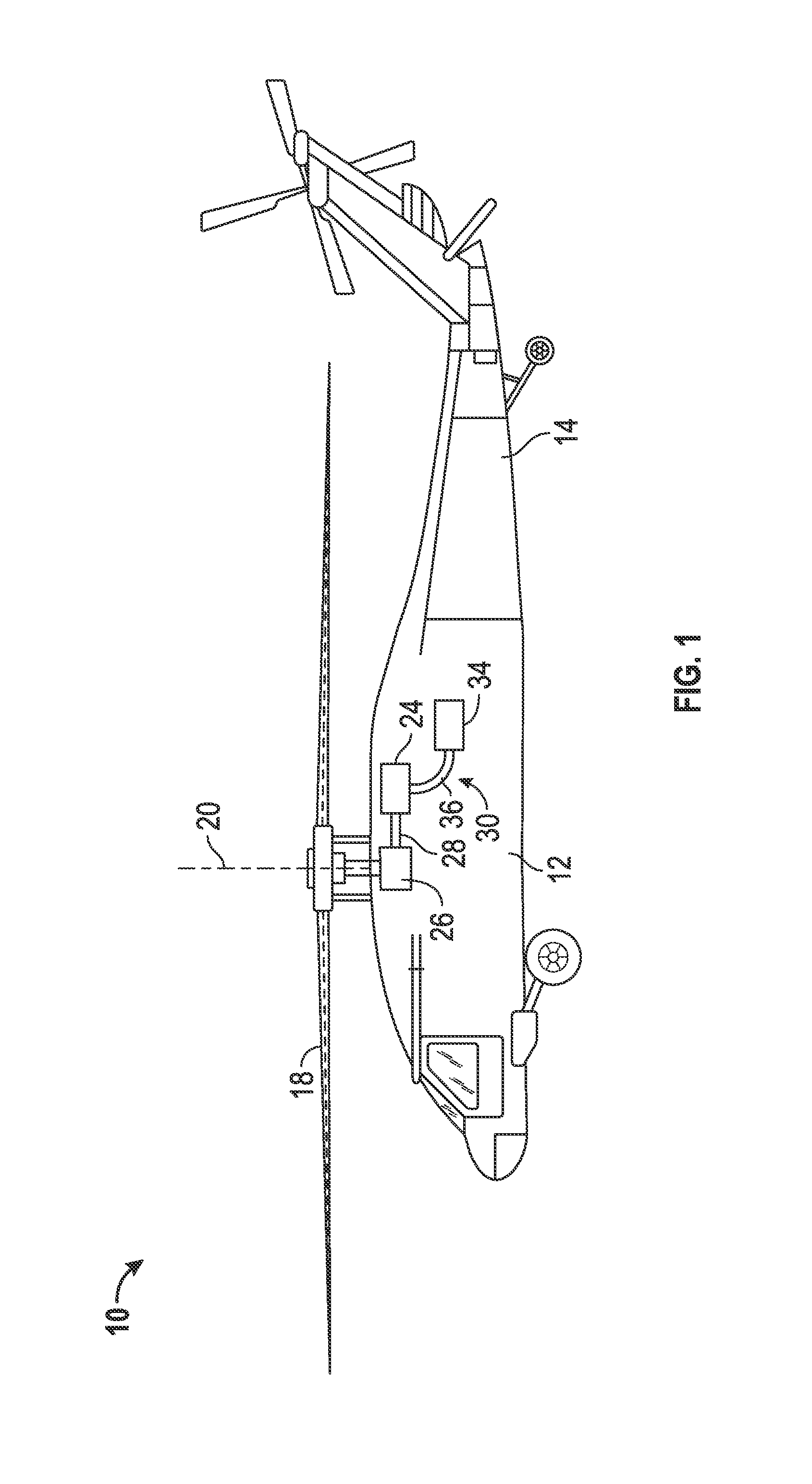
[0019]Shown in FIG. 1 is a schematic view of an embodiment of a rotary wing aircraft, in this embodiment a helicopter 10. The helicopter 10 includes an airframe 12 with an extending tail 14. A main rotor assembly 18 is located at the airframe 12 and rotates about a main rotor axis 20. The main rotor assembly 18 is driven by a power source, for example, an engine 24, in some embodiments, a turboshaft engine, via a gearbox 26. The engine 24 is connected to the gearbox 26 via a drive shaft 28. A fuel feed system 30 provides fuel to the engine 24.

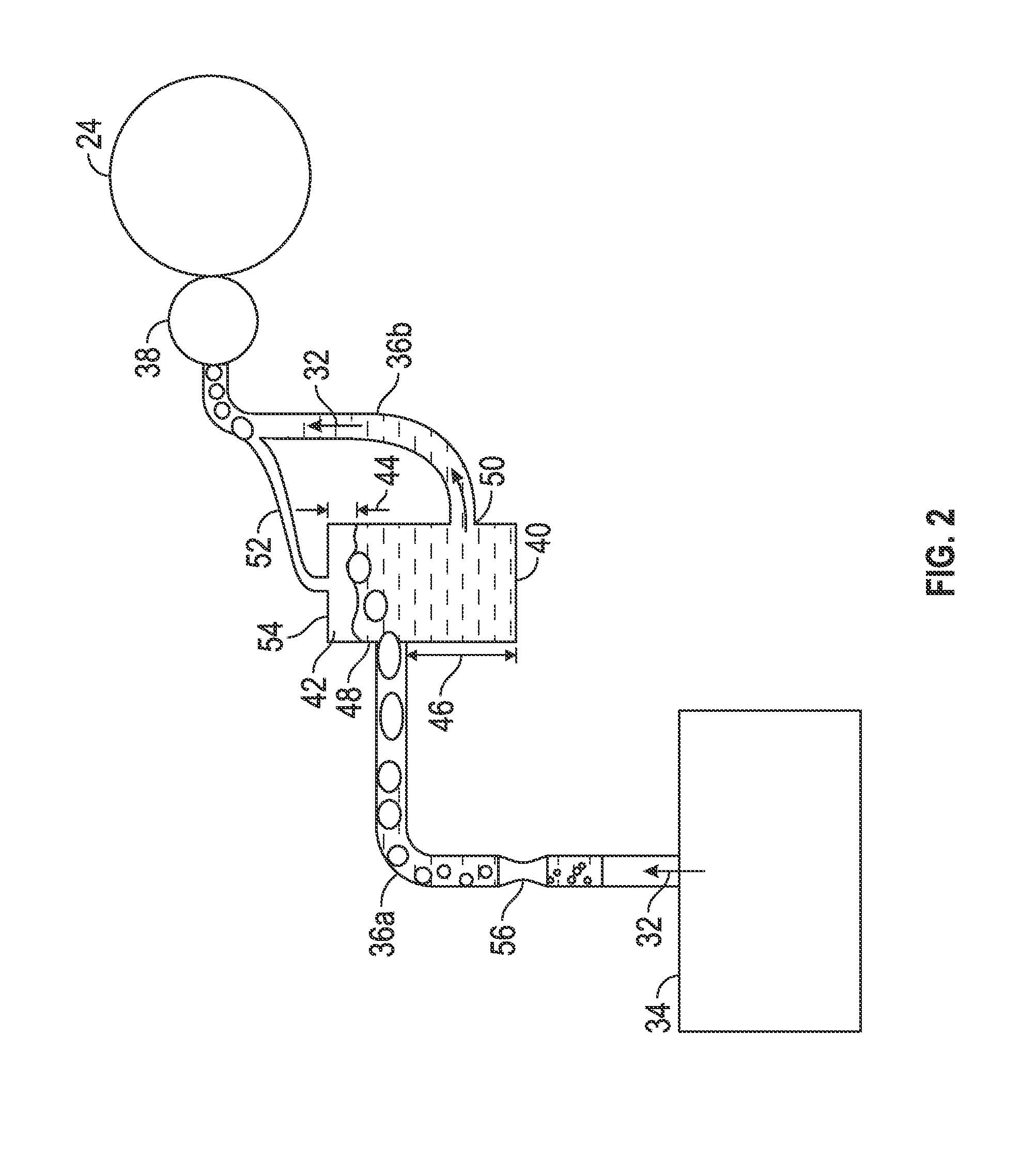
[0020]Referring now to FIG. 2, the fuel feed system 30 will be described in more detail. A flow of fuel 32 is drawn from a fuel tank 34 through a fuel line 36 toward the engine 24 via an engine fuel pump 38. The engine fuel pump 38 is a suction pump. Use of a suction pump ensures that the fuel line 36 is not pressurized during operation of the engine fuel pump 38, such that a rupture or failure of the fuel line 36 will result in air being drawn...


PUM


Abstract

A fuel feed system for a rotary-winged aircraft includes a fuel feed line extending from a fuel source to an engine and an engine fuel suction pump disposed at the fuel feed line to urge a flow of fuel through the fuel feed line to the engine. A collector is located along the fuel feed line between the fuel source and the engine to collect air-vapor bubbles which form in the flow of fuel. An air-vapor line extends from the top of the collector and merges with the fuel line section between the collector and the engine fuel pump. The air-vapor line is sized and configured to limit the flow of air-vapor from the collector to the engine fuel suction pump to a rate which the engine fuel suction pump can tolerate.

Description

FEDERAL RESEARCH STATEMENT[0001]This invention was made with government support under contract number N00019-06-C-0081 awarded by the United States Navy. The government has certain rights in the invention.BACKGROUND[0002]The subject matter disclosed herein relates to aircraft. More specifically, the subject matter disclosed herein relates to suction fuel feed systems for aircraft.[0003]Aircraft, for example, helicopters, include fuel feed systems having fuel lines and plumbing components which carry fuel from the fuel tanks to the engines. In modern helicopters, the engines are typically mounted higher up than the fuel tanks. Suction type engine fuel feed systems utilize a suction pump mounted on the engine which draws fuel up from the fuel tank. Suction type fuel feed systems are used in many helicopters because of the safety they provide. In the event of a fuel feed line leak, such as a rupture due to ballistic damage, air is drawn into the fuel line rather than fuel spraying out ...

Claims


Application Information

Patent Timeline
IPC IPC(8): F02M25/08B64D37/00B64C27/00F02M37/02
CPCF02M25/0872F02M37/02B64C27/00B64D37/005F02M25/089B64D37/04F02M37/20B64D37/22
Inventor SMITH, DAVID R.SHIELDS, DANIEL JOHN
Owner SIKORSKY AIRCRAFT
Learn More