Method for manufacturing plated laminate, and plated laminate

a technology of plated laminate and plated laminate, which is applied in the direction of coupling contact members, contact member manufacturing, etc., can solve the problems of peeling of silver plating, difficult plate silver, etc., and achieve superior abrasion resistance, slidability, and low frictional properties.

Active Publication Date: 2016-09-01
ORIENTAL MEKKI
View PDF9 Cites 13 Cited by
  • Summary
  • Abstract
  • Description
  • Claims
  • Application Information

AI Technical Summary

Benefits of technology

[0032]According to the method for manufacturing a plated laminate relating to the present invention, a tin-plated / silver-plated laminate that has superior abrasion resistance, electrical conductivity, slidability and low frictional property, and, that is suitable for suppression of embrittlement of the plated layer, and a manufacturing method thereof can be provided. Further, the tin-plated / silver-plated laminate of the present invention can be suitably used as a material for a connecting terminal requiring superior abrasion-resistant characteristic and electrical conductivity, and a connecting terminal combines superior abrasion resistance and electrical conductivity, and fitting properties can be provided.

Problems solved by technology

However, it is extremely difficult to plate silver, which is noble metal, on tin, which is base metal, and displacement between tin and silver occurs due to a potential difference between tin and silver occurs (diffused from each other), and peel-off of silver plating or the like happens to occur.
The technique is to alloy tin and silver by heating, and poor adhesion between tin plating and silver plating is not a serious problem (in other words, this is not a technology to laminate excellent silver plating on tin plating).

Method used


Image

  • Method for manufacturing plated laminate, and plated laminate
  • Method for manufacturing plated laminate, and plated laminate
  • Method for manufacturing plated laminate, and plated laminate

Examples


first embodiment

(1) First Embodiment

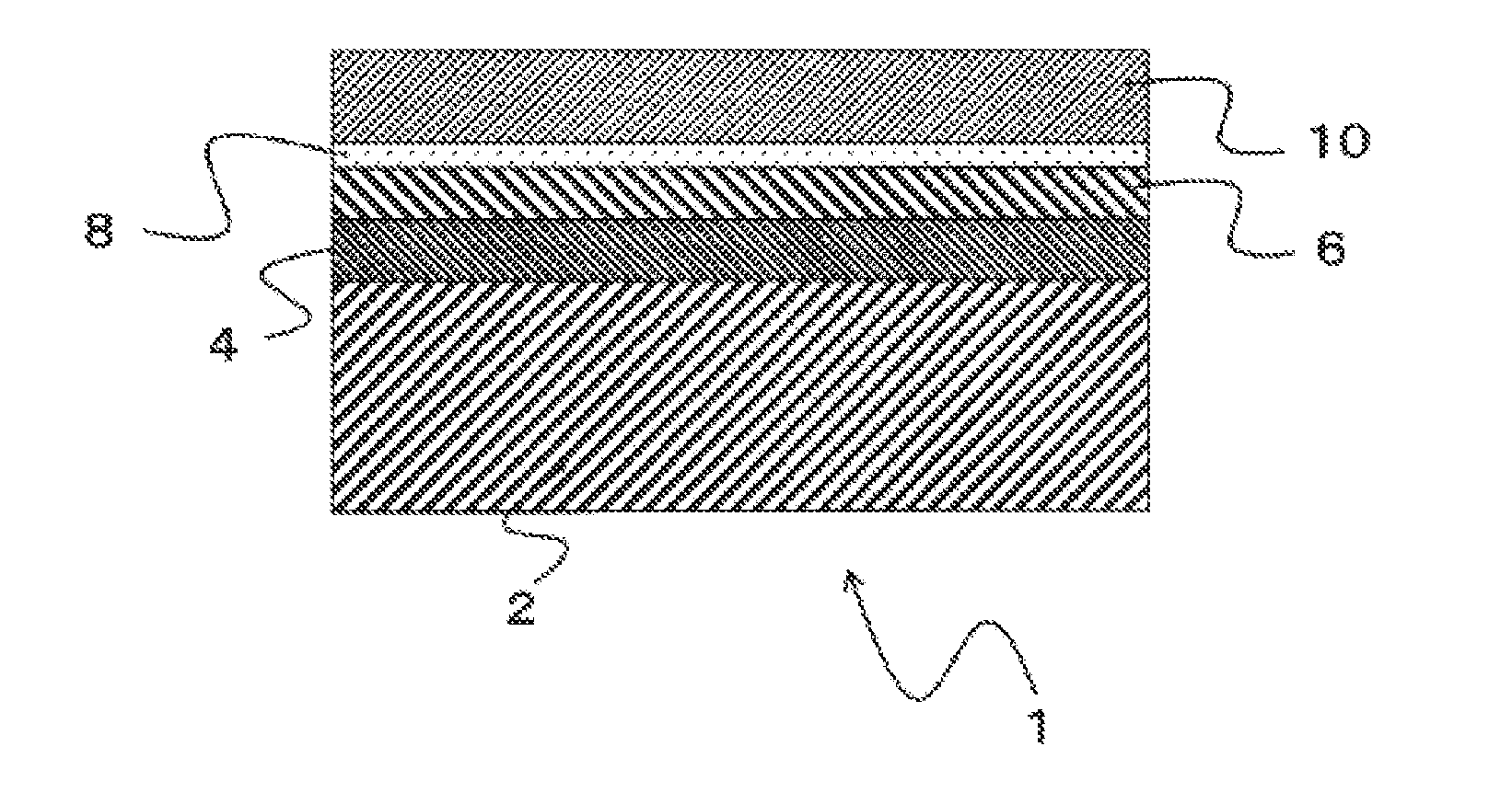
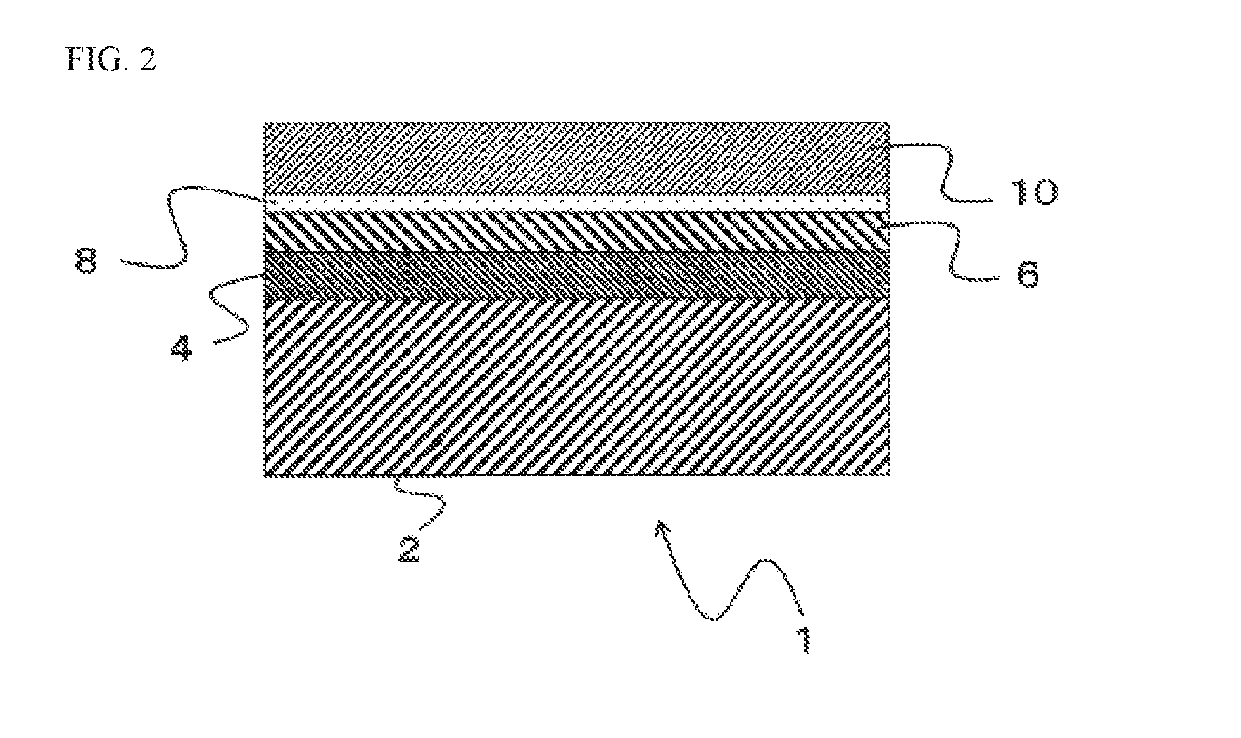
[0117]FIG. 2 is a schematic cross-sectional view of the First Embodiment of the plated laminate of the present invention. In a plated laminate 1, a tin-plated layer 4 is formed on the metal substrate 2, and a nickel-plated layer 6 is formed over the entire surface of the tin-plated layer 4. In addition, a silver strike-plated layer 8 is formed over the entire surface of the nickel-plated layer 6, and a silver-plated layer 10 is formed over the entire surface of the silver strike-plated layer 8. Furthermore, a silver strike-plated layer as similar to the silver strike-plated layer 8 is formed between the tin-plated layer 4 and the nickel-plated layer 6, as needed (not shown).

[0118]A metal of the metal substrate 2 is not particularly limited as long as having electrical conductivity, and for example, aluminum and aluminum alloy, iron and iron alloy, titanium and titanium alloy, stainless, copper and copper alloy and the like can be exemplified, and among them, it i...

second embodiment

(2) Second Embodiment

[0123]FIG. 3 is a schematic cross-sectional view of the Second Embodiment of the plated laminate of the present invention. In the plated laminate 1, the tin-plated layer 4 is formed on the surface of the metal substrate 2, and the nickel-plated layer 6 is formed on the entire surface of the tin-plated layer 4. In addition, the silver strike-plated layer 8 is formed on the entire surface of the nickel plated layer 6, and the silver-plated layer 10 is formed on a portion of the surface of the silver strike-plated layer 8. Furthermore, except for the formation of the silver-plated layer 10 on a portion of the silver strike-plated layer 8, it is similar to the First Embodiment.

third embodiment

(3) Third Embodiment

[0124]FIG. 4 is a schematic cross-sectional view of the Third Embodiment of the plated laminate of the present invention. In the plated laminate 1, the tin-plated layer 4 is formed on the surface of the metal substrate 2, and the nickel plated layer 6 is formed on a portion of the surface of the tin-plated layer 4. In addition, the silver strike-plated layer 8 is formed over the entire surface of the nickel plated layer 6, and the silver-plated layer 10 is formed over the entire surface of the silver strike-plated layer 8. Furthermore, except for the formation of the nickel-plated layer 6 on a portion of the surface of the tin-plated layer 4, the formation of the silver strike-plated layer 8 over the entire surface of the nickel-plated layer 6 and the formation of the silver-plated layer 10 over the entire surface of the silver strike-plated layer 8, it is similar to the First Embodiment.


PUM

PropertyMeasurementUnit
Vickers hardnessaaaaaaaaaa
thicknessaaaaaaaaaa
thicknessaaaaaaaaaa

Abstract

Provided are: a tin-plated/silver-plated laminate, which has excellent abrasion resistance, electrical conductivity and slidability and a low frictional property, and whereby it becomes possible to prevent the embrittlement of a plating layer contained therein; and a method for producing the tin-plated/silver-plated laminate. The present invention is a method for producing a plated laminate by forming a silver plating layer on a tin plating layer that is formed on the surface of a metallic base material, said method being characterized by comprising: a first step of subjecting an arbitrary region in the surface of a tin plating layer to a nickel plating treatment, thereby forming a nickel plating layer; a second step of subjecting an arbitrary region in the surface of the nickel plating layer to a silver strike plating treatment; and a third step of subjecting at least a part of the surface region of the nickel plating layer, which has been subjected to the silver strike plating treatment, to a silver plating treatment.

Description

TECHNICAL FIELD[0001]The present invention relates to a method for manufacturing a plated laminate and a plating laminate obtained using the manufacturing method, and more specifically, a tin-plated / silver-plated laminates that have superior abrasion resistance, electrical conductivity, slidability and low frictional property, and, that are suitable for suppressing embrittlement of a plated layer, and a manufacturing method thereof.BACKGROUND TECHNOLOGY[0002]Silver plating has superior characteristics in low contact resistivity, heat resistance and the like, and is widely utilized for electric / electronic components, such as various contacts, terminals, connectors or switches (for example, see Patent Literature 1 (Japanese Patent Application Laid-Open No. 2001-3194)).[0003]Recently, electric cars, plug-in hybrid cars and the like have become popular, and in association with this, battery chargers, such as battery chargers for household use or rapid battery chargers, also become popul...

Claims


Application Information

Patent Timeline
Patent Type & Authority Applications(United States)
IPC IPC(8): H01R13/03C25D3/46C25D5/12H01R43/16C25D3/48C25D3/50C25D3/38C25D5/14C25D3/12C25D5/34
CPCC25D3/50C25D3/38C25D5/14H01R43/16C25D3/48C25D3/12C25D3/46C25D5/12C25D5/34H01R13/03C25D5/50C25D5/617
Inventor TAKAHASHI, HIROYOSHI
Owner ORIENTAL MEKKI
Why Eureka
Try Eureka