PFC Current shaping

a current shaping and current technology, applied in the field of pfc current shaping, can solve the problems of reducing harmonics/ripples, generating too high harmonics at higher power levels, and passive pfc choke solutions having limitations in power loss and size, and efficiently damping the resonance circuit. , the effect of dynamic resistan

Active Publication Date: 2016-09-01
DELTA ELECTRONICS (THAILAND) PUBLIC CO LTD
View PDF9 Cites 4 Cited by
  • Summary
  • Abstract
  • Description
  • Claims
  • Application Information

AI Technical Summary

Benefits of technology

[0021]A further advantage of the invention is, that the dynamic resistance more efficiently damps the resonance circuits that are formed by the reactive elements of the grid and the EMI capacitors of the power supply.
[0022]In the case of a negative value I0 the reference current becomes lower wherefore the power drawn from the grid would decrease compared with a conventional or standard PFC circuit if the magnitude Î of the reference signal would be generated with the same value as in the standard PFC circuit. In order to achieve the same output power of the power supply unit, the magnitude Î of the reference signal Iref has to be increased. In another example where the reference current is increased by adding as positive value T0 the magnitude Î of the reference signal Iref has to be decreased to draw about the same power from the grid.
[0023]In a preferred embodiment of the invention, and in order to achieve a same output power of the power supply unit using a standard reference signal Is=Îs*sin(ωt) having a standard magnitude Îs, i. e. where I0=0, the magnitude Î of the reference signal is generated by modifying the standard magnitude Îs in dependency of a change of the output power of the power supply unit due to adding the value I0 to the reference signal Iref, in particular to compensate said change of the output power.
[0024]The magnitude Î may for example be set by trial and error. However, the value of the magnitude Î is preferably determined by a comparison of the power that may be drawn from the grid with a standard PFC circuit and a comparable PFC circuit according to the invention. The term comparable in this connection means that the PFC circuit of the invention differs from the standard PFC circuit just in the generation of the reference signal by adding the value I0 and adapting the magnitude Î of the reference signal accordingly.
[0025]In a standard PFC circuit the following applies:P_s(ϕs1,ϕs2)=1ϕs2-ϕs1·∫ϕs1ϕs2U^·I^s·sin2(ϕ)·ϕwhere Û and Îs are the magnitudes of the grid voltage and current, φs1 and φs2 are the power transfer angles which are usually φs1=0 and φs2=π and where Ps is the power drawn from the grid. By solving the integral, this power can be rewritten as:P_s(ϕs1,ϕs2)=U^·I^s2·[1-sin(2·ϕs2)2·(ϕs2-ϕs1)+sin(2·ϕs1)2·(ϕs2-ϕs1)].
[0026]Generally speaking, the power transfer angles are those angles between which a current flow occurs. So the first angle, here φs1 is the angle where the current flow starts and the second angle, here φs2 is the angle where the current flow ends.

Problems solved by technology

But for a three-phase input, for example a grid having three lines but no neutral conductor it may create too high harmonics at higher power levels.
The passive PFC choke solution has however limitations regarding power loss and size whereas the other solution is suitable for higher power levels only, i. e. for power levels up to approximately 2 kW.
Another drawback of the prior art solutions is that they do not actively damp the resonance circuits that are formed by the grid impedances in conjunction with the EMI capacitors that are often provided between the phase lines and the neutral conductor of the power supplies input filter.
Load variations at the output of the power supply lead to input current variations which excite such resonance circuits which may lead to undesired high input voltages that may even lead to a malfunction or destruction of the power supply.

Method used


Image

  • PFC Current shaping
  • PFC Current shaping
  • PFC Current shaping

Examples


Embodiment Construction

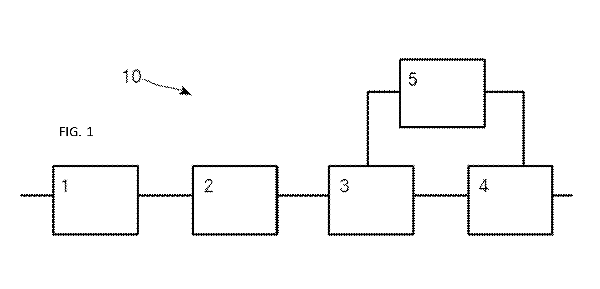
[0068]FIG. 1 shows a schematic depiction of a PFC circuit 10 according to the invention. The first block represents the power grid 1 to which the PFC circuit 10 is connected. The second block represents the input filter 2, the third block represents the bridge rectifier 3, the fourth block represents the converter 4 and the fifth block represents the control circuit 5 that generates the reference signal for the input current of the converter 4.

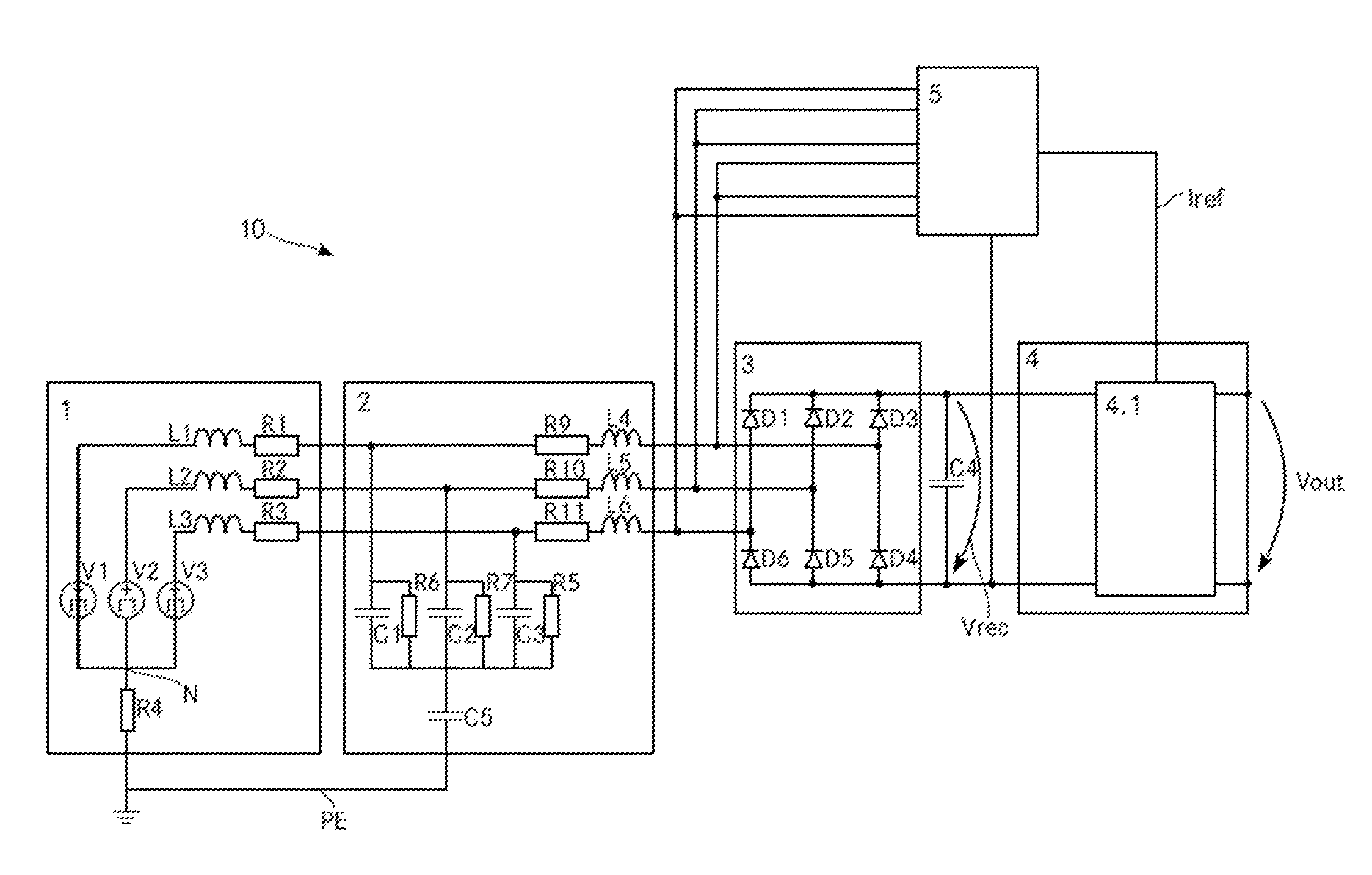
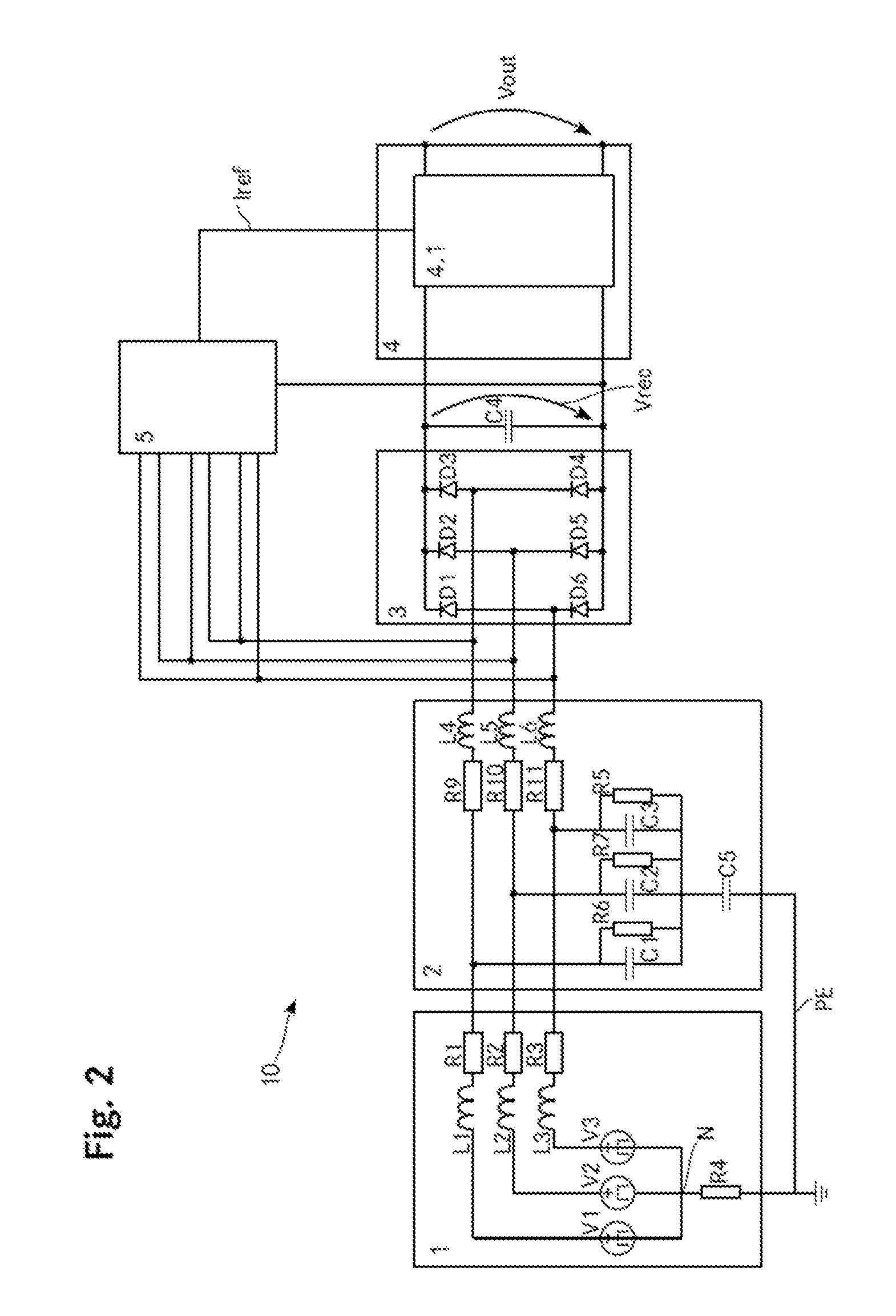
[0069]FIG. 2 shows a more detailed schematic depiction of the PFC circuit 10 shown in FIG. 1. The power grid 1 has three phase lines, a neutral connector N which is optional and a protective earth line PE. The phase lines have line-to-neutral voltages V1, V2, V3 and the impedances L1, L2 and L3 as well as the resistors R1, R2, R3 represent the grid impedance.

[0070]The input from the grid 1 is fed to the input filter 2. The input filter 2 includes three X-capacitors C1, C2, C3 connected between each phase line and the protective earth line PE. ...


PUM


Abstract

A PFC circuit according to the invention is connected to a grid, includes an input filter and a rectifier connected to a converter. A control circuit generates the reference current for the current regulator of the converter that controls its input current. Thereby, the reference current is generated by adding an offset current (I0) to a standard reference current and adapting the magnitude of the standard reference current to compensate for a change of the input power resulting from the addition of the offset current (I0). However, due to the addition of the offset current (I0) the magnitudes of some lower harmonic components of the input current of the power supply unit are increased and the magnitudes of some higher harmonic components of the input current are decreased such that the power supply may draw more current from the grid.

Description

TECHNICAL FIELD[0001]The invention relates to a method for generating a reference signal for a current regulator of a PFC circuit of a power supply unit. The invention also relates to a PFC circuit including such a current regulator and a power supply unit including such a PFC circuit. Further, the invention relates to a corresponding control circuit for generating a reference signal for a current regulator of a PFC circuit of a power supply unit.BACKGROUND ART[0002]Electrical appliances are usually connected to a power grid to be fed with the electrical power to operate them. Often, such appliances include a power supply unit to convert the electrical power delivered by the grid into a specific form of electrical power that may be used by the appliance itself or that may be further provided to another device connected to the appliance.[0003]In order to limit undesired feedback into the grid, such appliances usually have to fulfil some requirements regarding the current drawn from t...

Claims


Application Information

Patent Timeline
Patent Type & Authority Applications(United States)
IPC IPC(8): H02M1/42H02M1/12H02M1/44
CPCH02M1/42H02M1/12H02M1/44H02J3/01H02M1/4216H02M1/4225H02M1/4208Y02B70/10H02M1/4291H02M1/0025
Inventor KRUMPHOLZ, CHRISTIAN
Owner DELTA ELECTRONICS (THAILAND) PUBLIC CO LTD
Why Eureka
Try Eureka