Equipment with a detachable accessory and assembly for a machining lathe, and machining lathe with digital control

a technology of machining lathes and accessories, applied in the direction of driving apparatus, attachment devices for boring/drilling, manufacturing tools, etc., can solve the problems of time-consuming and complicated manual adjustments, inability to produce shapes by such a procedure, and the disadvantage of using these devices is also found on another type of additional equipment, so as to reduce costs and save space. , the effect of saving weigh

Active Publication Date: 2016-09-08
USINES TORNOS FAB DE MACHINES MOUTIER
View PDF12 Cites 14 Cited by
  • Summary
  • Abstract
  • Description
  • Claims
  • Application Information

AI Technical Summary

Benefits of technology

[0008]One object of the features of the invention is to make it possible for a lathe to offer more machining possibilities requiring only prior operations (adjustment or the like) which are simple to carry out.
[0010]A lathe equipped with an equipment in accordance with the invention also has the advantage of being highly versatile. This high level of versatility does not need to be associated with an increased take-up of space within the cabinet of the lathe since the invention makes it possible for there not to be as many supports fixed to the frame of the lathe as there are usable machining accessories.
[0011]The high level of versatility achieved by the invention also does not need to be associated with an excessive increase in complexity in the machining lathe itself since this lathe can make use of more devices than it incorporates. For example, the lathe to which the invention is applied can make use of a device for forming polygons and then a thread cutter without being permanently equipped with both at the same time.
[0013]The tool support system with integrated drive advantageously comprises means allowing rapid fixing of the detachable accessory at the mounting location.
[0014]The equipment advantageously comprises a permanent drive device comprising engaging means making it possible to establish a kinematic connection to communicate drive from this permanent drive device to the detachable accessory. When such is the case, the detachable accessory does not need to have its own motorisation means, which can translate into a simplification in particular of the electric cabling, reduced costs, a saving in terms of weight and / or a saving in terms of space.

Problems solved by technology

Some shapes cannot be produced by such a procedure.
Machining operations using these devices require prior manual adjustments which are time-consuming and complicated.
The same disadvantage is also found on another type of additional equipment, i.e. devices for forming polygons which serve to produce pieces with a polygonal cross-section.

Method used


Image

  • Equipment with a detachable accessory and assembly for a machining lathe, and machining lathe with digital control
  • Equipment with a detachable accessory and assembly for a machining lathe, and machining lathe with digital control
  • Equipment with a detachable accessory and assembly for a machining lathe, and machining lathe with digital control

Examples


Embodiment Construction

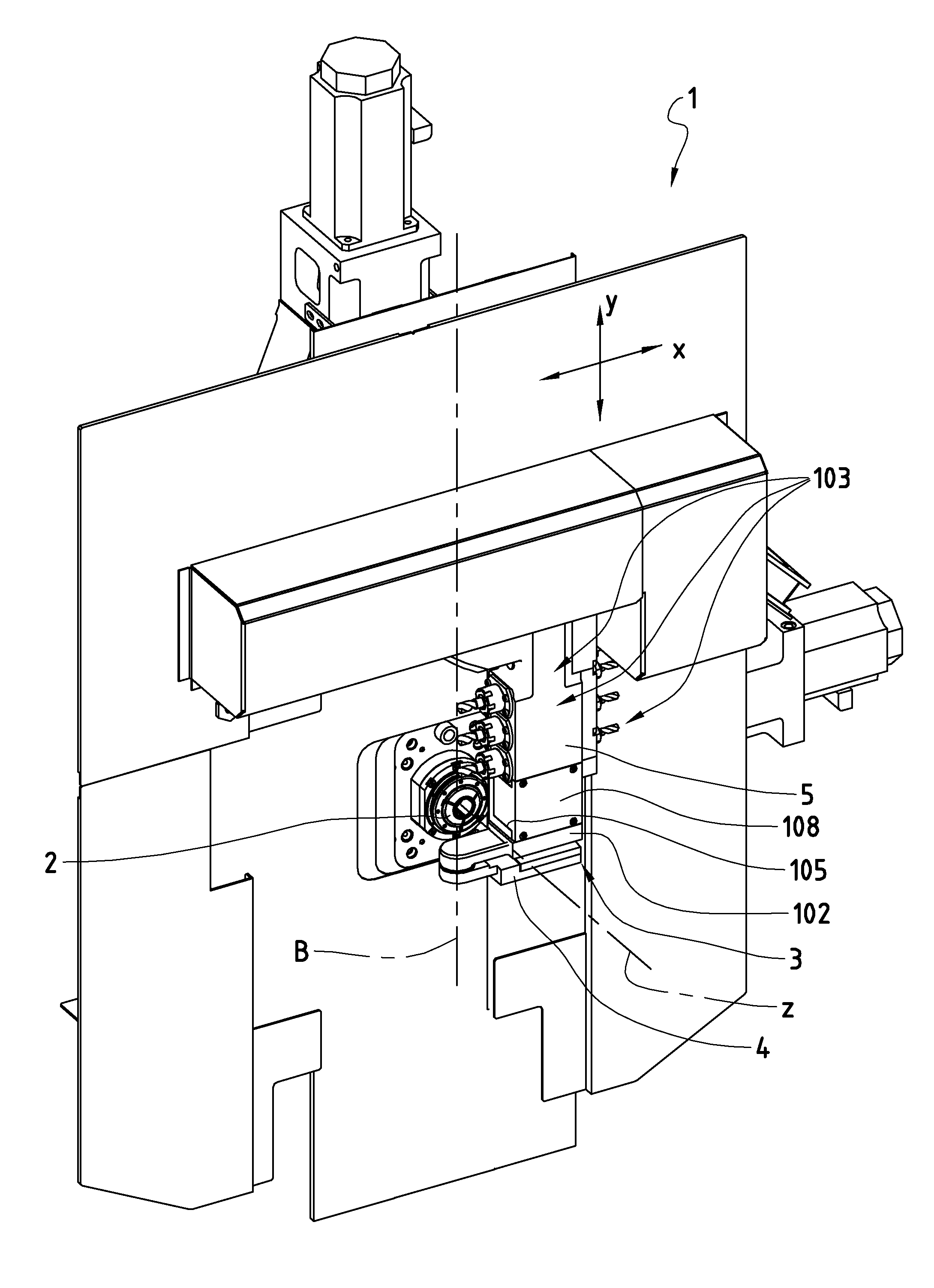
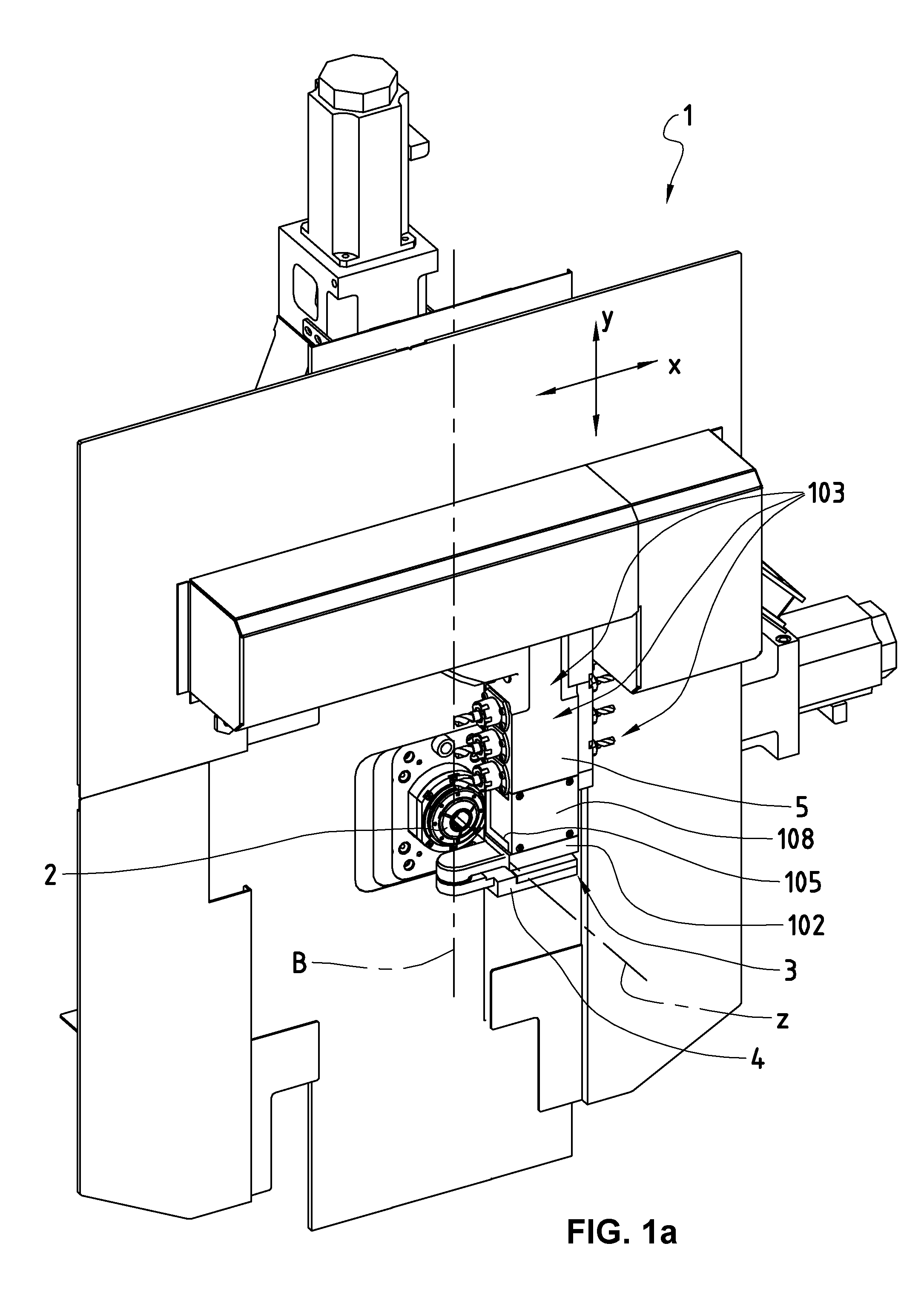
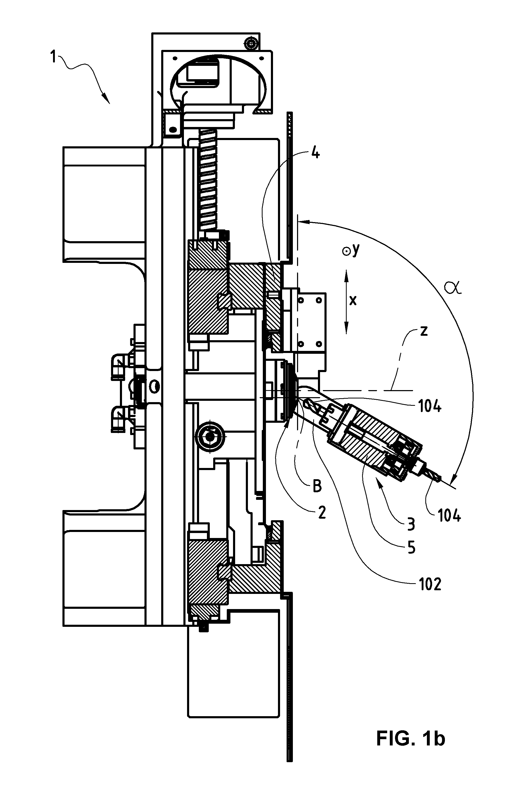
[0030]In FIG. 1 as in FIG. 2, only some constituent parts of a lathe with digital control 1 in accordance with the invention are shown, the parts of this lathe 1 which are not shown being known per se. The lathe 1 comprises a rotary mandrel 2, the axis of rotation of which is referenced Z and which is provided to support and rotationally drive a material to be machined, not shown.

[0031]The lathe 1 also comprises an equipment 3 which is in accordance with the invention while being of the so-called “B axis” type of equipment. The equipment 3 comprises a movable carriage 4 which can be displaced in a vertical plane in two perpendicular translational directions, i.e. a horizontal translational direction X and a vertical translational direction Y. The movable carriage 4 is guided and displaced in the X and Y translational directions by means which are well known to the person skilled in the art. When the movable carriage 4 is also displaceable in a translational direction in parallel wit...


PUM

PropertyMeasurementUnit
movementsaaaaaaaaaa
shapesaaaaaaaaaa
timeaaaaaaaaaa

Abstract

An equipment for a machining lathe with digital control comprising a movable carriage, a tool support system with integrated drive which is mounted so as to pivot on this movable carriage so as to be able to pivot about a pivot axis, as well as a device for actuating the tool support system with integrated drive with respect to the movable carriage. The tool support system with integrated drive comprises at least one mounting location to detachably receive a detachable accessory to support and drive a tool.

Description

TECHNICAL FIELD OF THE INVENTION[0001]The present invention relates to the field of machining using a lathe with digital control. More precisely, it relates to an equipment and an assembly for a machining lathe with digital control, as well as to such a machining lathe with digital control.PRIOR ART[0002]Most machining operations carried out by a lathe take place by rotating the material to be machined with respect to a tool which cuts into the material passing in front of it by reason of this rotation.[0003]Some shapes cannot be produced by such a procedure. This is the case e.g. with lateral flats or with holes which have an axis inclined with respect to the axis of rotation of the mandrel for holding and driving the material to be machined.[0004]A lathe with digital control can comprise an additional equipment by virtue of which, while the piece being manufactured is still held in the lathe, it is possible to produce, on this piece, inclined holes or lateral flats which could not...

Claims


Application Information

Patent Timeline
Patent Type & Authority Applications(United States)
IPC IPC(8): B23B11/00B23B43/00
CPCB23B43/00B23B11/00B23Q3/00B23Q5/12B23B39/162B23B3/065B23Q1/623B23Q39/022
Inventor THEURILLAT, MARC
Owner USINES TORNOS FAB DE MACHINES MOUTIER
Why Eureka
Try Eureka