Anti-icing system for an aircraft

Active Publication Date: 2016-09-08
SHORT BROTHERS
View PDF1 Cites 11 Cited by
  • Summary
  • Abstract
  • Description
  • Claims
  • Application Information

AI Technical Summary

Benefits of technology

This patent describes an improved anti-icing system for aircraft that uses less hot gas to achieve the same level of protection. The system uses a swirl-inducing device to mix the hot gas from the nozzle with the air from the chamber, resulting in a more uniform temperature distribution and improved anti-icing efficiency. The system is relatively lightweight and can reduce ice formation without adding significant weight to the aircraft.

Problems solved by technology

Aircraft parts may be subject to ice formation, in particular forward-facing surfaces.
Ice that has formed on an aircraft part may alter aerodynamic properties of the aircraft and increase aircraft weight.
This may lead to an increase in fuel consumption or require a different control of the aircraft, or both.
Most severely, ice formation may lead to a loss of control over the aircraft.
Moreover, a piece of ice that has formed may break off and damage an aircraft part.
Such damage may then lead to one of the aforementioned consequences.
However, a piccolo duct adds weight to the aircraft, which causes an increase in fuel consumption.

Method used


Image

  • Anti-icing system for an aircraft
  • Anti-icing system for an aircraft
  • Anti-icing system for an aircraft

Examples


first embodiment

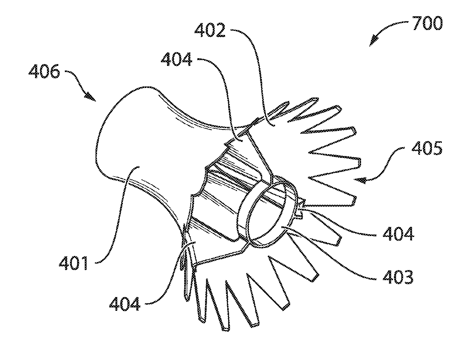
[0048]FIGS. 4-6 schematically illustrate the gas-mixing device 214 which will be referred to as first gas-mixing device 400 hereinafter for reasons of convenience. FIG. 4 schematically illustrates a perspective view of the first gas-mixing device 400. FIG. 5 schematically illustrates a side view of the first gas-mixing device 400. FIG. 6 schematically illustrates a front view of the first gas-mixing device 400.

[0049]The first gas-mixing device 400 is in the form of a sleeve-like structure, which comprises a main sleeve 401. An inner surface 402 of the main sleeve 401 defines an airflow channel The first gas-mixing device 400 further comprises a mounting sleeve 403 for mounting the first gas-mixing device 400 on a nozzle, such as the nozzle 213 illustrated in FIGS. 2 and 3. The main sleeve 401 is fixed to the mounting sleeve 403 by means of various fixation fins 404.

[0050]The mounting sleeve 403 is located at an inlet 405 of the first gas-mixing device 400. In more detail, FIG. 5 sch...

second embodiment

[0057]FIGS. 10-12 schematically illustrate the gas-mixing device 214, which will be referred to as second gas-mixing device 1000 hereinafter for reasons of convenience. FIG. 10 schematically illustrates a first perspective view of the second gas-mixing device 1000. FIG. 11 schematically illustrates a second perspective view of the second gas-mixing device 1000. FIG. 12 schematically illustrates a front view of the second gas-mixing device 1000.

[0058]The second gas-mixing device 1000 has some similarities with the first gas-mixing device 400 described hereinbefore. The second gas-mixing device 1000 is also in the form of a sleeve-like structure comprising a main sleeve 401 of which an inner surface 402 defines an airflow channel The second gas-mixing device 1000 further also comprises a mounting sleeve 403 for mounting the second gas-mixing device 1000 on a nozzle 213, such as the nozzle 213 illustrated in FIGS. 2 and 3.

[0059]Further similarities are as follows. The mounting sleeve 4...


PUM


Abstract

An anti-icing system is provided within a chamber having an exterior wall of which an outer surface may be subject to ice formation. The anti-icing system comprises a nozzle arranged to inject hot gas within the chamber. A gas-mixing device defines a channel for receiving hot gas from the nozzle. The gas-mixing device includes a swirl-inducing feature for causing gas from the chamber to be drawn into the channel with a swirling effect when hot gas from the nozzle is injected into the channel.

Description

CROSS REFERENCE TO RELATED APPLICATIONS[0001]This application claims priority to U.S. Patent Application No. 61 / 895,450, filed Oct. 25, 2013, the disclosure of which is incorporated by reference herein in its entirety.FIELD OF THE INVENTION[0002]An aspect of the invention relates to an anti-icing system. The anti-icing system may be applied in, for example, an aircraft, in particular for preventing ice formation on an inlet lip skin of an engine nacelle. Other aspects of the invention relate to an aircraft and a method of anti-icing an aircraft.BACKGROUND OF THE INVENTION[0003]Aircraft parts may be subject to ice formation, in particular forward-facing surfaces. For example, ice may form on an inlet lip skin of an engine nacelle during flight. Ice that has formed on an aircraft part may alter aerodynamic properties of the aircraft and increase aircraft weight. This may lead to an increase in fuel consumption or require a different control of the aircraft, or both. Most severely, ice...

Claims


Application Information

Patent Timeline
IPC IPC(8): B64D15/04B64D33/02
CPCB64D15/04B64D2033/0233B64D33/02F02C7/047F05D2240/127F05D2260/601
Inventor NEWMAN, RICHARDMCCAUSLAND, MICHAEL
Owner SHORT BROTHERS
Why Eureka
Try Eureka