Mission agnostic space vehicle

a space vehicle and mission technology, applied in the field of mission agnostic space vehicles, can solve the problems of prohibitively high cost of developing, designing and building a space vehicle for any purpose, requiring significant lead time, and the same design cannot typically be re-used in association with dissimilar mission profiles. , to achieve the effect of easy customization of emissivity, and reducing cost per uni

Active Publication Date: 2016-09-08
YORK SPACE SYST LLC
View PDF8 Cites 8 Cited by
  • Summary
  • Abstract
  • Description
  • Claims
  • Application Information

AI Technical Summary

Benefits of technology

[0018]Aspects of embodiments of the present invention include systems, apparatuses and methods associated with the construction configuration and use of a space vehicle to reduce cost per unit and increase payload capacity. Certain embodiments of the present invention incorporate novel configuration and thermal management strategies to provide a mission-agnostic space vehicle platform.
[0019]Embodiments of the invention include, but are not limited to, central mounting configurations, launch vibration isolation, easily customizable emissivity through the use of surface coatings, pressurized component enclosure, working fluids within a pressurized component enclosure, and fans driving a semi-passive convective thermal management system.

Problems solved by technology

Space vehicle technology generally has provided widely used and useful technology, but remains prohibitively expensive to develop, design, and construct a space vehicle for any purpose.
Furthermore, developers typically develop space vehicle technologies optimized specifically for a single mission, requiring significant lead time.
An associated challenge, therefore, is that the same design cannot typically be re-used in association with dissimilar mission profiles.
Each space vehicle is a custom built unique piece of hardware, with the associated high costs and applicability of use associated with such specialization.
A recurring challenge associated with space vehicles relates to thermal management, which plays a major role in the design of space vehicles.
This challenge relates to the lack of atmosphere in the operating range of satellites and other space vehicles.
As a result, a space vehicle may experience a surface temperature exceeding allowable operational temperatures of component electronic equipment.
Furthermore, a surface of a space vehicle not exposed to solar radiation results in a surface temperature well below desirable operational temperatures of components.
Both hot and cold temperatures in these scenarios introduce expensive design criteria for the manufacturer.
A problem with some space vehicles is that components are mounted directly to externally facing panels.
Thus, such panels experience potentially damaging operational temperature swings based on situational orientation in relation to solar radiation.
The problems associated with such systems include problems associated with cost, complexity, weight, and reliability.
Such systems are expensive to implement.
They may occupy critical weight and volume that could otherwise be utilized by additional components and / or payload systems.
The failure of such systems results in malfunction or failure of on-board systems, providing an additional point of failure and decreasing overall reliability and life span of the space vehicle.
This is problematic, as such systems add weight, numerous failure mechanisms, and cost to the build of the space vehicle.
Thus, such systems limit the functional payload capacity that can be integrated within a given space vehicle structure.
Furthermore, considerable engineering costs must be expended in order to evaluate and reduce failure modes, not including the need to tailor each platform to the specific mission of each space vehicle build.
Given the discussion of aforementioned problems associated with space vehicles, the development and deployment of associated space vehicle technology based platforms remains cost prohibitive, heavy in nature, and / or have time intensive lead-time associated with it.

Method used


Image

  • Mission agnostic space vehicle
  • Mission agnostic space vehicle
  • Mission agnostic space vehicle

Examples


Embodiment Construction

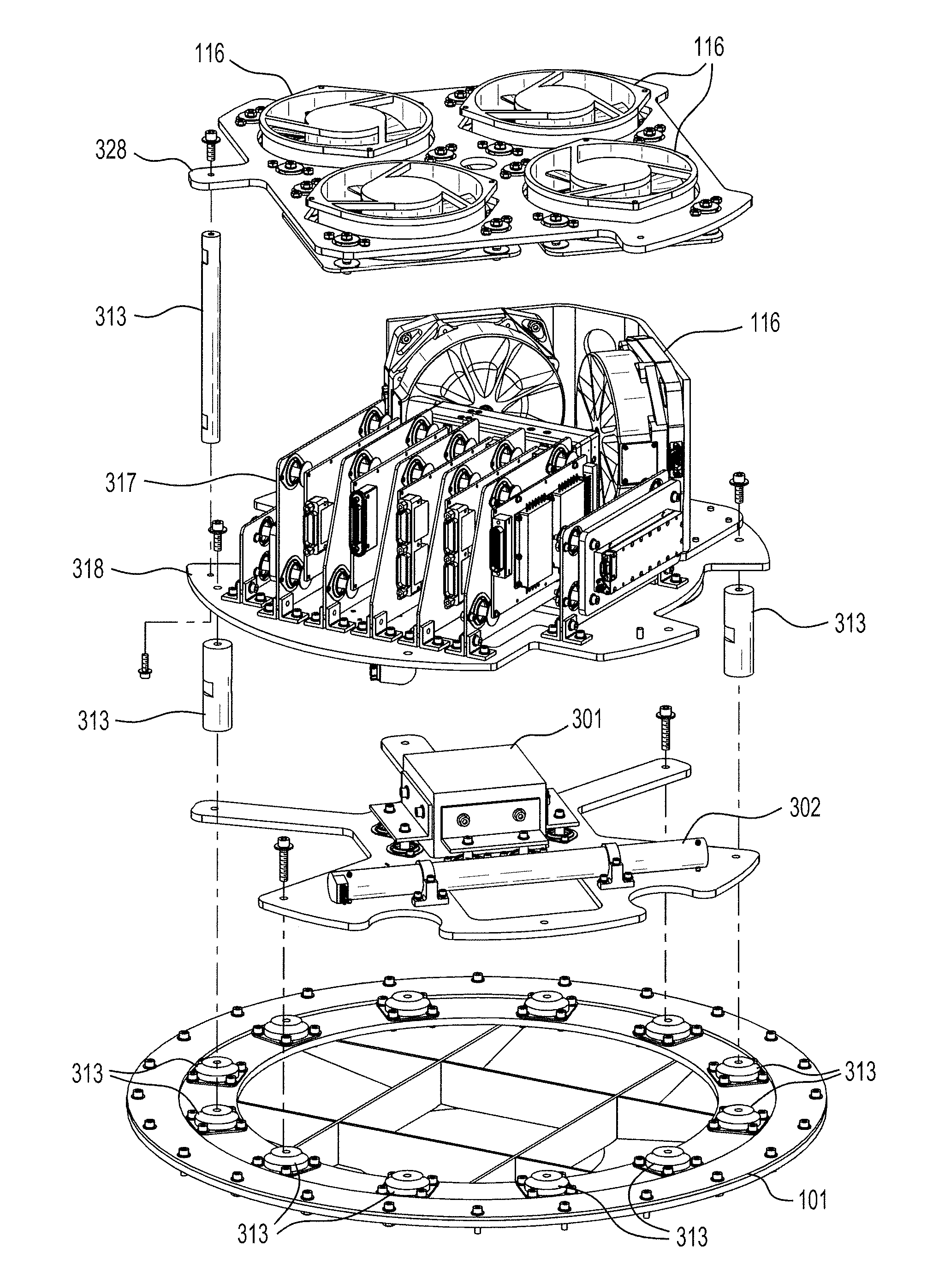
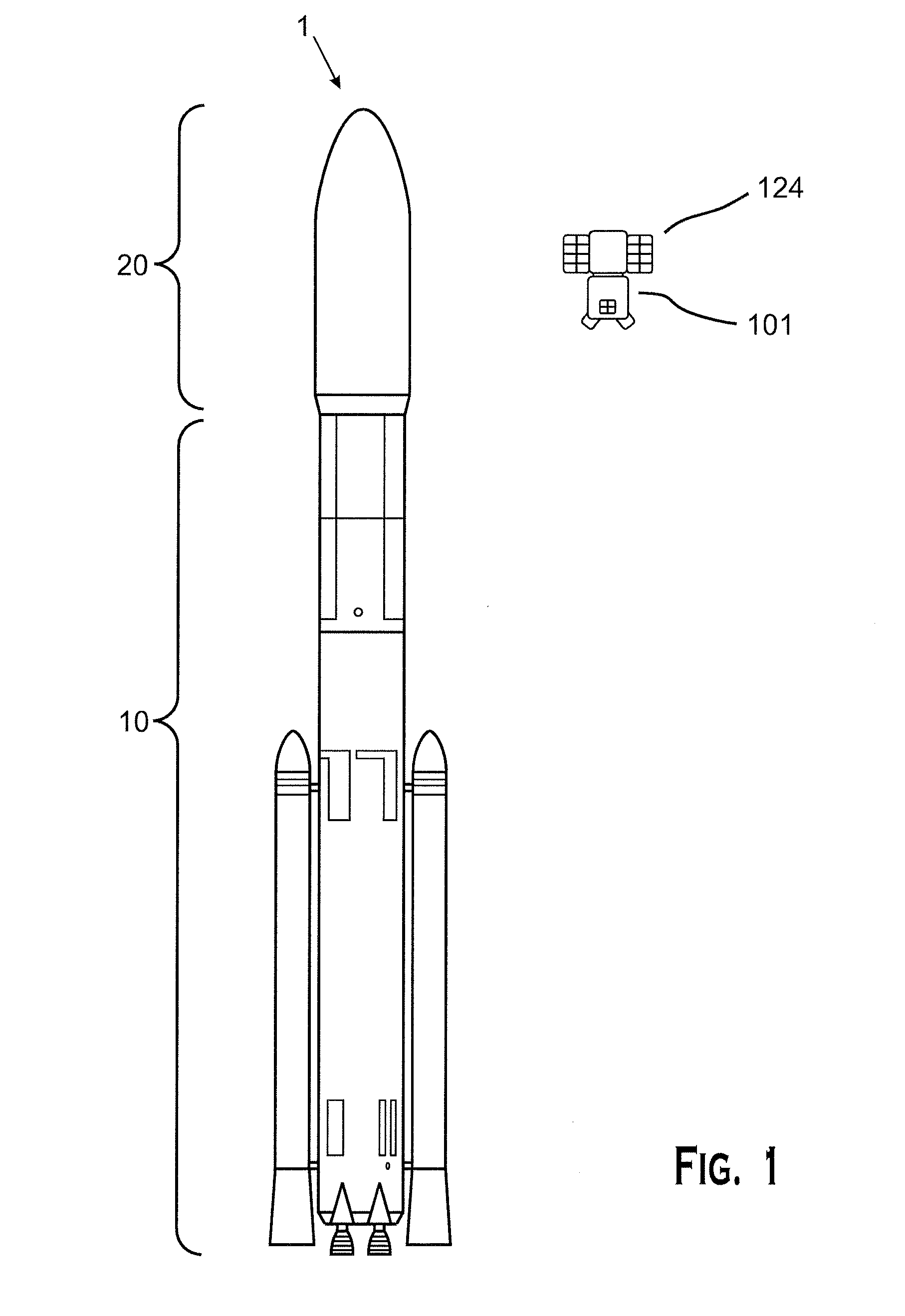
[0044]Aspects of the invention address one or more problems associated with the manufacture of space vehicles. The embodiments of the invention disclosed herein are typically associated with space vehicles bound for earth orbit, often in the form of what are referred to as “Satellites.” A certain embodiment of the invention comprises a mission-agnostic space vehicle platform intended to reduce costs associated with the use of such space vehicles. With reference to FIG. 1, a rocket 1 can be comprised of two segments: a launch segment 10 and a space segment 20. After the launch of the rocket 1, the launch segment 10 can be discarded while the space segment 20 continues on to its designated mission. The space segment 20 further comprises a spacecraft bus 101 and a payload 124. The spacecraft bus 101 includes many of the electronic components that will be required during a mission, and will often include components that are commonly required across a variety of missions. The payload 124...


PUM


Abstract

A compartment for a space vehicle includes a pressurized structure having a structural wall, the structural wall having interior surfaces facing an interior of the compartment and exterior surfaces exposed to an external environment. An internal mounting structure for mounting a component is provided within the compartment, and mounting features support the internal mounting structure from the pressurized structure. The internal mounting structure is spaced away from the interior surfaces of the pressurized structure, and a thermal fluid is provided in the pressurized structure. The thermal fluid enables convective heat transfer between the component mounted on the internal mounting structure and the interior surfaces of the pressurized structure.

Description

[0001]This application claims priority under 35 U.S.C. §119 to U.S. Provisional Patent Application No. 62 / 127,359, filed on Mar. 3, 2015, which is incorporated by reference herein in its entirety.FIELD OF THE INVENTION[0002]The present invention relates generally to mission agnostic space vehicles.BACKGROUND OF THE INVENTION[0003]Today, over 1,100 functioning satellites orbit our Earth in addition to approximately 2,600 decommissioned satellites. These currently functioning space vehicles provide a wide range of services including Global Positioning System (GPS) navigation aid, telephone communications, television broadcast, weather forecasting, and defense-oriented purposes. Space vehicle technology generally has provided widely used and useful technology, but remains prohibitively expensive to develop, design, and construct a space vehicle for any purpose.[0004]A space vehicle, as used herein, may include various configurations. For instance, a space vehicle may consist of a space...

Claims


Application Information

Patent Timeline
Patent Type & Authority Applications(United States)
IPC IPC(8): B64G1/22B64G1/66B64G1/10
CPCB64G1/22B64G2001/228B64G1/66B64G1/10B64G1/002B64G1/50B64G1/503B64G1/641B64G1/228H05K7/20218H05K7/203H05K7/20245
Inventor WALLINGER, DIRK
Owner YORK SPACE SYST LLC
Why Eureka
Try Eureka